Pet scanner and image reconstruction method thereof

a pet scanner and image reconstruction technology, applied in tomography, instruments, nuclear engineering, etc., can solve the problems of difficult to accurately localize a cancer site, difficult to confirm accurately whether irradiation has been performed in accordance with treatment plans or not, and deviations are not easily detected, so as to suppress the deterioration of image quality and easy to gain access

Inactive Publication Date: 2010-05-27
NAT INST FOR QUANTUM & RADIOLOGICAL SCI & TECH
View PDF11 Cites 35 Cited by
  • Summary
  • Abstract
  • Description
  • Claims
  • Application Information

AI Technical Summary

Benefits of technology

[0025]The present invention has been made in order to solve the above-described conventional problems, and an object of which is to provide a PET scanner capable of suppressing the deteriorated quality of an image and also securing an open space for easily gaining access to a patient and fixing a medical device as well as to provide a method for the image reconstruction thereof.

Problems solved by technology

It was, however, difficult to accurately localize a site of cancer, if the cancer was found, due to the shortage of anatomical information.
However, in reality, it is difficult to confirm accurately whether irradiation has been performed in accordance with treatment plans or not.
If the patient is positioned wrongly to result in deviation of the irradiation field, the deviation is not easily detected.
However, this type of PET scanner is insufficient in sensitivity due to the limited solid angle of a detector, with no widespread use.
The detector sensitivity is generally considered insufficient.
These factors cause mental and physical burdens to patients and are also one of the reasons that medical institutions cannot lower examination costs.
However, there is such a problem that a long patient port further increases the closed nature of the port, thereby causing psychological stress to patients.
A situation in which a patient under PET scanning is not visually confirmed for health conditions is not desirable also for medical personnel who perform PET scanning.
The long patient port causes problems in these experiments as well.
However, since the detectors are not to block particle beams, it was difficult to arrange the detectors on the PET scanner in such a manner as to meet simultaneously the above-described two conditions.
Gamma camera opposition-type PET scanners can be easily arranged so as not to block particle beams 22 irradiated from a therapeutic radiation controller 20 but definitely hold a disadvantage in that the detector sensitivity is fundamentally lower.
However, the slit lacks necessary information for image reconstruction because of the presence of the slit, resulting in the deteriorated quality of an image, which is regarded as a problem (P. Crespo, et al., “On the detector arrangement for in-beam PET for hadron therapy monitoring,” Phys. Med. Biol. Journal, vol.
There is found a potential problem that the same site is not determined during the same session by PET and X-ray CT.
However, a discrepancy between PET images and X-ray CT images on the chest which entails the deformation by respiration is found.
This discrepancy is now recognized as a serious problem.
Therefore, a site apart at a greater distance than the FOV in the body axis direction cannot be imaged theoretically during the same session.
Although there are problems such as complicated data processing, the greatest reason for the limited FOV in the body axis direction is the increased equipment cost due to a greater number of detectors.
Further, since each of the PET scanners makes an independent coincidence determination, no detection can be made for the radiation from a nuclide present at a region between the scanners, thus resulting in a failure in imaging the region between the scanners.
However, where this idea is applied as it is to a PET scanner so that detectors are arranged sparsely on a ring, the coincidence line necessary for image reconstruction is lacking to inevitably result in the deteriorated quality of an image.

Method used


Image

  • Pet scanner and image reconstruction method thereof
  • Pet scanner and image reconstruction method thereof
  • Pet scanner and image reconstruction method thereof

Examples


first embodiment

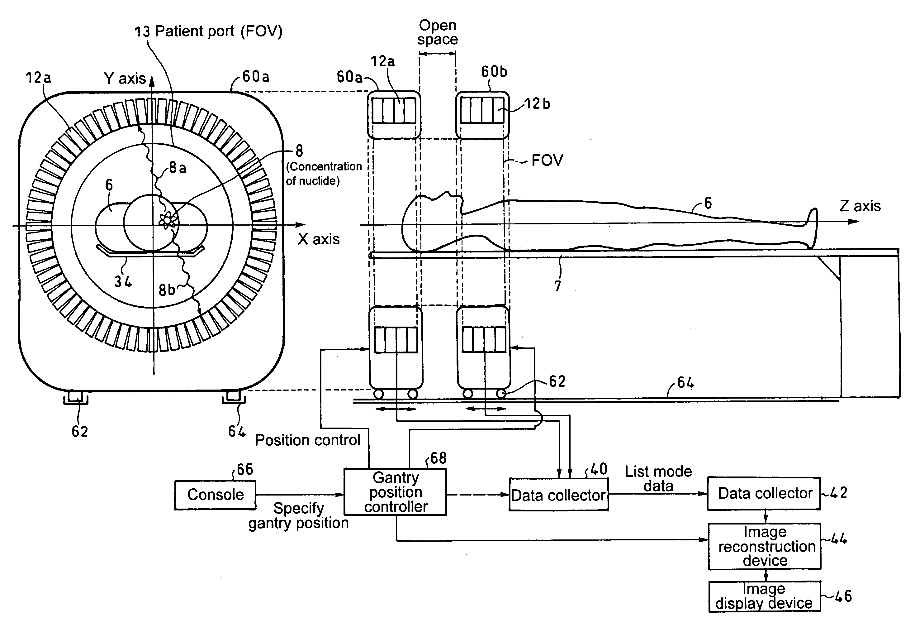
[0073]As shown in FIG. 10, in the present invention, a first detector ring 12a and a second detector ring 12b in which detectors 10 arranged densely or spatially in a ring shape or in a polygonal shape are arranged, with an open space kept in the body axis direction, coincidences are measured for some of or all of detector pairs connecting the first detector ring 12a with the second detector ring 12b to perform three-dimensional image reconstruction, thereby imaging as a tomographic image an open space between the first detector ring 12a and the second detector ring 12b.

[0074]FIG. 11 is a flow chart illustrating processing procedures in a constitution having two detector rings, that is, the detector ring 12a and the detector ring 12b.

[0075]For the sake of explanatory convenience, a region which is imaged as a tomographic image is divided into three regions, that is, a first FOV within the detector ring 12a, a second FOV within the detector ring 12b, and an open space (also referre...

second embodiment

[0084]Next, a description will be given in detail for the present invention by referring to FIG. 16.

[0085]The present embodiment is a PET scanner similar to that of the first embodiment, in which not only coincidences are measured for some of or all of detector pairs connecting a first detector ring 12a and a second detector ring 12b but also coincidences are measured for some of or all of detector pairs within the first detector ring 12a and some of or all of detector pairs within the second detector ring 12b to perform the three-dimensional image reconstruction. Thereby, a continuous region which combines a first FOV of the first detector ring 12a, a second FOV of the second detector ring 12b and an open space is imaged as tomographic images.

[0086]FIG. 17 illustrates procedures for obtaining tomographic images which combine the clearance region, the first FOV and the second FOV in the second embodiment. Coincidences are determined within the detector ring 12a and within the detect...

third embodiment

[0092]In the third embodiment, allowable ranges between the first FOV, the second FOV, and the clearance region can be obtained as illustrated in FIG. 22. Specifically, when the ring diameter of the first detector ring 12a is given as D1, the width of the sensitivity area in the body axis direction is given as W1, the ring diameter of the second detector ring 12b is given as D2, the width of the sensitivity area in the body axis direction is given as W2, and the clearance between detector rings is given as G, following formulae can be used to calculate W, H1 and H2 in the drawing.

W=(D1×W2+D2×W1) / (D1+D2)  (1)

H1=D1×(G+W2) / (D1+D2)  (2)

H2=D2v(G+W1) / (D1+D2)  (3)

[0093]Then, where the relationship of H1>W or H2>W or G>W is satisfied, as illustrated in FIG. 22 (A), a region is developed that is not imaged, by which a FOV in the body axis direction is made discontinuous. Therefore, as illustrated in FIG. 22 (B), in order to secure a FOV which is continuous in the body axis direction, it is n...


PUM


Abstract

A plurality of detector rings in which detectors arranged densely or spatially in a ring shape or in a polygonal shape are arranged, with an open space kept in the body axis direction, coincidences are measured for some of or all of detector pairs connecting the detector rings apart from the open space to perform three-dimensional image reconstruction, thereby imaging the open space between the detector rings as a tomographic image. Therefore, the open space is secured, with the deteriorated quality of an image suppressed, thus making it possible to easily gain access to a patient under PET scanning from outside a gantry and also provide irradiation of particle beams for cancer treatment as well as X-ray CT scanning.

Description

TECHNICAL FIELD[0001]The present invention relates to positron emission tomography equipment (also called a positron CT scanner and hereinafter referred to as a PET scanner) in which a radiopharmaceutical labeled with a positron emission nuclide is injected into the body, each pair of annihilation (gamma) photons resulting from decay of positrons is determined according to the principle of coincidence, and image reconstruction is performed to image the spatial and temporal distribution of the radiopharmaceutical. The present invention relates, in particular, to an open-type PET scanner capable of securing open spaces inside the scanner and also to an image reconstruction method thereof.BACKGROUND ART[0002]PET (Positron Emission Tomography) is a method for injecting radiopharmaceuticals labeled with a positron emission nuclide into the body to image the spatial and temporal distribution of the radiopharmaceuticals. In particular, PET scanning in which a radiopharmaceutical called flu...

Claims


Application Information

Patent Timeline
Patent Type & Authority Applications(United States)
IPC IPC(8): G06T7/00G01T1/161H05G1/60
CPCG01T1/1611G01T1/1615A61B6/037A61B6/03G01T1/2985G01T1/1603
Inventor YAMAYA, TAIGAMURAYAMA, HIDEOMINOHARA, SHINICHI
Owner NAT INST FOR QUANTUM & RADIOLOGICAL SCI & TECH
Why Eureka
Try Eureka