Patient Alignment in MRI Guided Radiation Therapy

a radiation therapy and guided radiation technology, applied in the field of patient alignment in guided radiation therapy, can solve the problems of increasing the possibility of secondary rt-induced cancer, significant impact of patient quality of life, and collapsing tissue damage, and achieves superior soft tissue contrast of mr, ensure patient safety, and ensure the accuracy of the guided radiation therapy procedur

Inactive Publication Date: 2013-09-12
IMRIS
View PDF8 Cites 36 Cited by
  • Summary
  • Abstract
  • Description
  • Claims
  • Application Information

AI Technical Summary

Benefits of technology

[0107]The critical advantage of the invention is that it provides a simple approach to calibrating the MR-to-Linac isocenter transformation each day, or before each treatment session, and enables automatic application of this transformation to subsequent MR images collected prior to treatment. This provides a method to ensure that the MR image datasets are in the Linac coordinates to enable expedient and accurate image matching and application of couch shifts to bring the patient position in line with the RT plan using the superior soft tissue contrast of MR.
[0108]Another advantage is that the tool provides a means to screen the images to ensure that the MR sequence and parameters are valid for imaged-guided RT, and that a corresponding MR guidance image dataset exists to guide therapy. This ensures both accuracy of the MR-based image-guidance procedure and patient safety, adding a redundant step to avoid operator error in the MR data collection.
[0109]A unique aspect of this invention is the overall workflow for aligning the MR coordinate system with the Linac coordinate system. The use of a phantom and calibration phase algorithm is novel, as is the concept to apply the transformation matrix to MR data collected at the time of treatment.
[0110]The arrangement disclosed herein provides the ability to perform MR imaging in the same room as external RT without RF interference from the RT system using a specific placement of RF-shielded doors between the two systems that open and close in between radiation therapy and MR imaging. This provides an arrangement aimed to directly combine MR with RT in a hybrid suite.
[0111]The arrangement described provides a movable MRI system that can be brought into the room to image the patient before treatment, and then retract the MRI system immediately prior to RT treatment. To implement this movable MRI system with external beam RT treatment requires a novel room configuration and specific shielding requirements to minimize the effects of the linear accelerator on MR image quality, and to ensure optimal operational characteristic of the linear accelerator.
[0112]As MR image formation is based on radiofrequency transmission (RF) and detection. MRI systems are typically enclosed within a RF-shielded room to prevent spurious RF signals, external to the MRI system, from interfering with the image acquisition. Depending on the sequence employed, external RF signals create unacceptable artifacts in the image that hinder diagnosis, and degrade the overall image quality. Any electronic devices in the RF-shielded room may be sources of RF, and interfere with image acquisition. Therefore, to combine MRI with RT requires that all devices within the RF-shielded room are RF quiet, i.e., do not generate detectable RF noise. In standard linear accelerators, a number of electronic devices exist that may generate RF noise. One solution to this problem of RF noise involves shutting off all electronic devices in the RT unit during MR imaging, and subsequently powering these devices on for RT treatment. However, this solution has several drawbacks. Thus critical components in the linear accelerator as well as onboard X-ray imaging systems require significant ‘warm up’ time. Accuracy of the RT system may be compromised by shorter ‘warm up’ times. Patient throughput is reduced. Repeated power cycling of the electronic components may reduce the overall lifetime of the system. Power up / power down may require additional calibration steps to ensure safe and accurate operation of the device. A better solution involves isolating the critical electronic components of the RT system from the MRI using a set of RF-shield doors between the MRI and RT system that are closed during MR imaging, and opened for radiation treatment.

Problems solved by technology

Although MRI provides good location of the tumour for treatment planning purposes, these treatment planning images are normally collected several days prior to treatment, and, as such, may not be completely representative of tumour location on the day of treatment.
However, this increased treatment margin also produces collateral tissue damage that may have a significant impact of the quality of life of the patient and increase the possibility of secondary RT-induced cancer.
However, this design is complex, expensive and may involve serious compromises on the functional performance of both the MRI and linear accelerator.
As such, the position of the tumour in the treatment imaging plans may not be representative of the actual lesion position on each day of treatment.
There has been wide-spread adoption of x-ray image-guided methods to position the patient ahead of each treatment fraction; however, x-ray imaging does not provide enough soft tissue contrast required to clearly identify the tumour.
One problem in the scenario of daily MR acquisition ahead of RT therapy, is a lack of correspondence between the MR imaging coordinate system, and the Linac coordinate system (determined by the intersection of the megavoltage (MV) beams of the linear accelerator positioned at different beam angles) due to use of a moving magnet.
But, this anatomical registration would have to be based on parts of the image not expected to change over time (such as the bony anatomy), which is extremely challenging and prone to errors.

Method used


Image

  • Patient Alignment in MRI Guided Radiation Therapy
  • Patient Alignment in MRI Guided Radiation Therapy
  • Patient Alignment in MRI Guided Radiation Therapy

Examples


Embodiment Construction

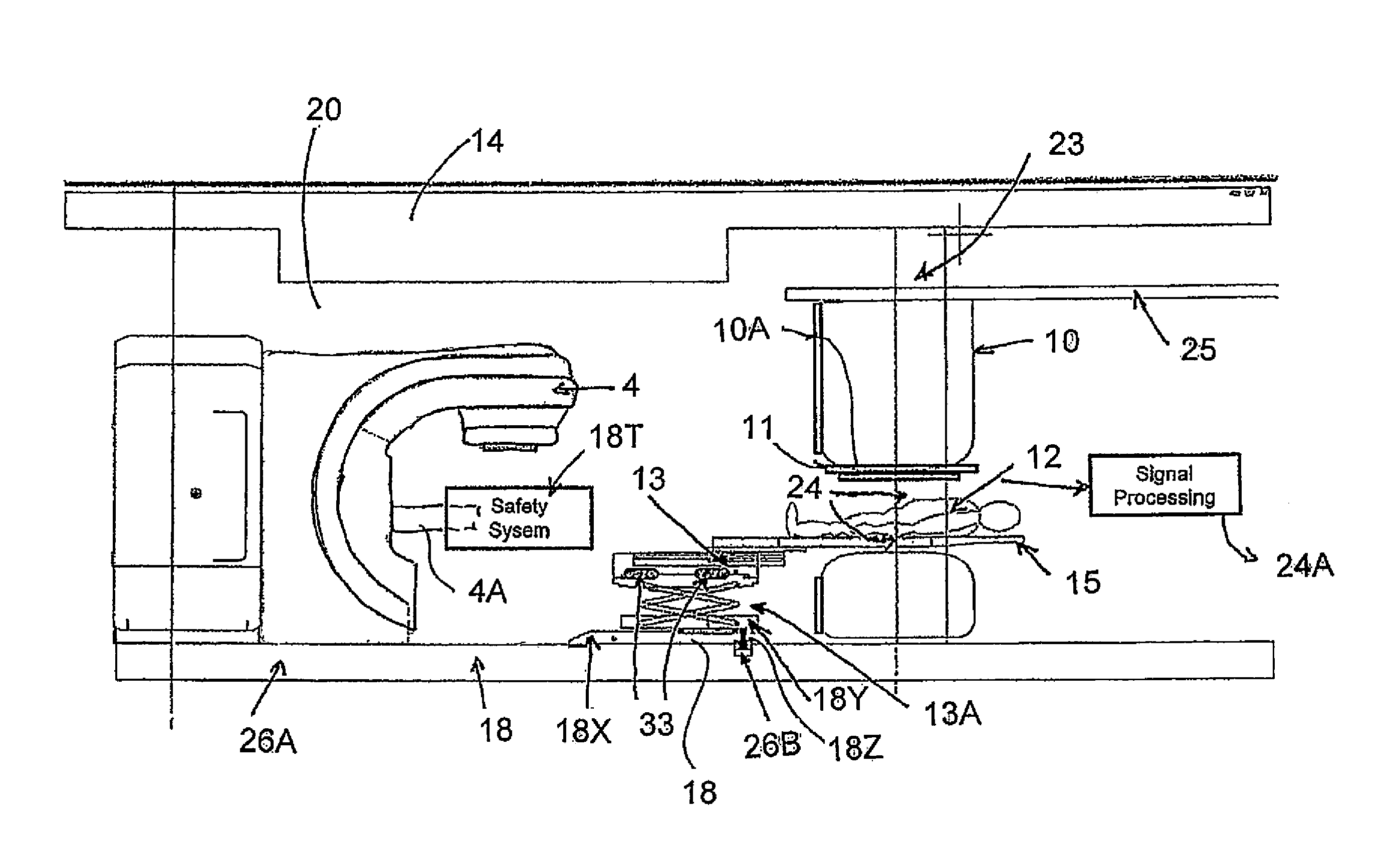
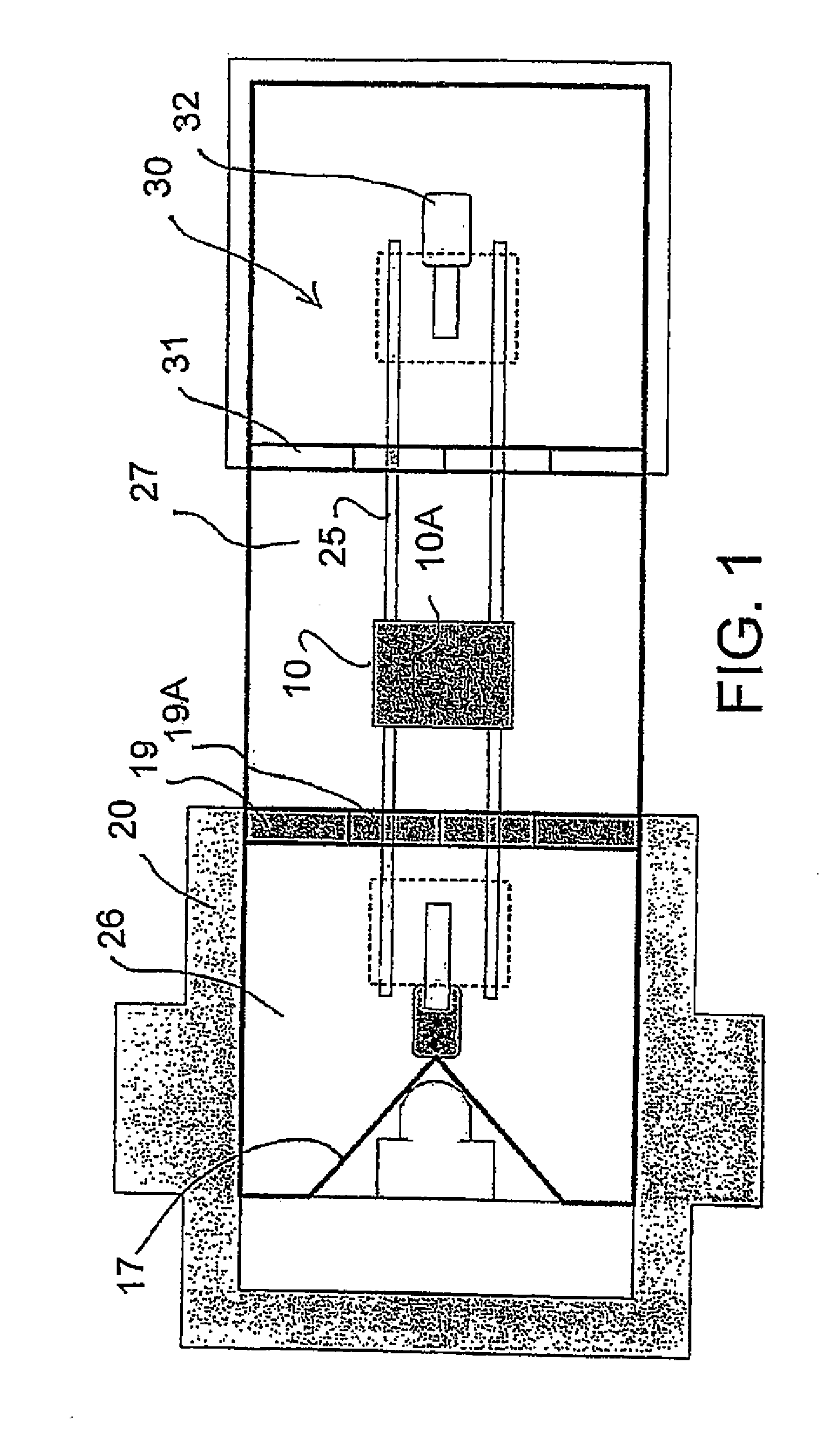
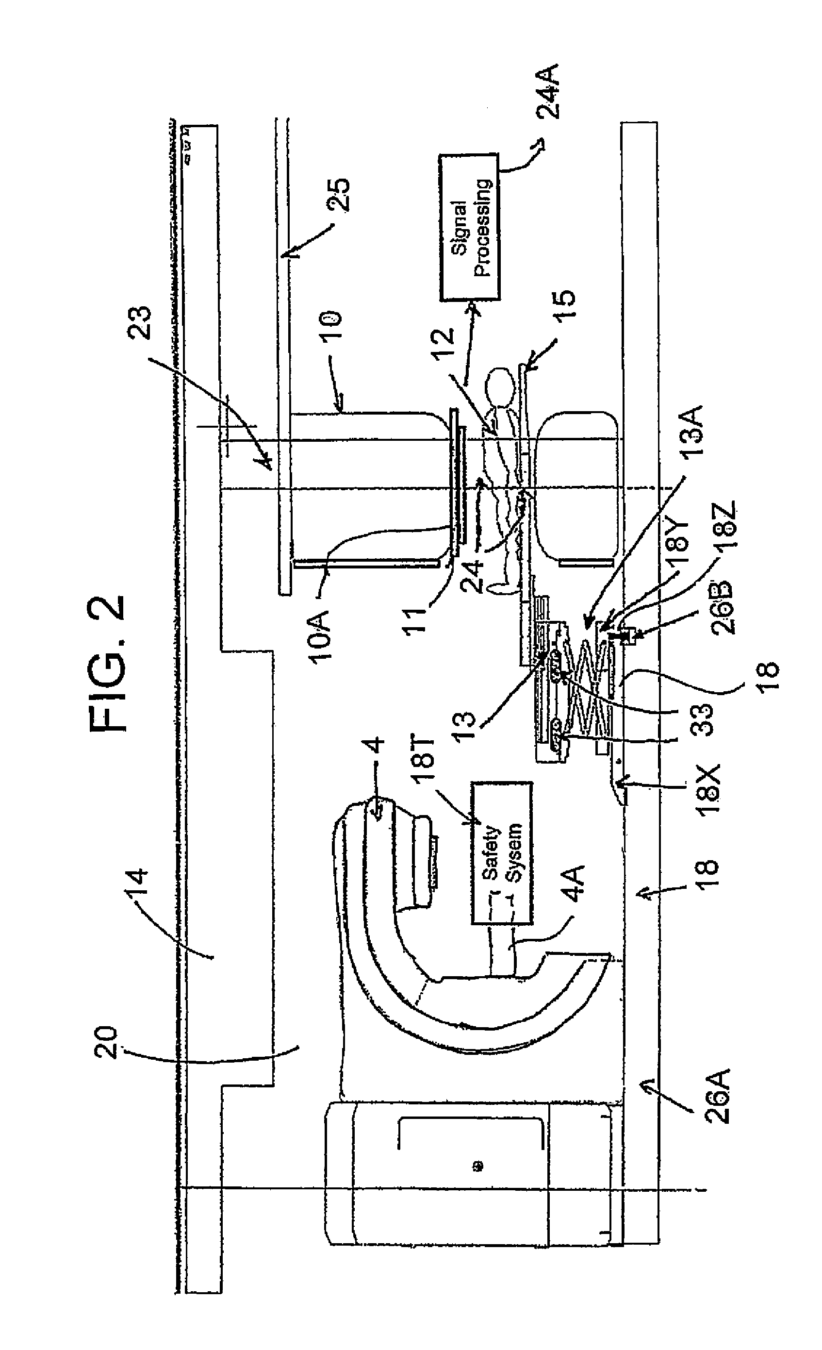
[0167]In FIGS. 1 to 5 is shown a schematic diagram of the MRI and external beam RT therapy system within the external beam bunker room configuration. This diagram includes a magnet 10, having a bore 10A into which a patient 12 can be received on a patient couch top 15, which is attached to a patient couch 13.

[0168]The movable magnet is carried on a rail system 25 with a support 23 suspended on the rail system. Further details of this construction are available from published US application 2008 / 0038712 published Feb. 14, 2008 assigned to the present assignees, the disclosure of which is incorporated herein by reference.

[0169]A suitable radiation therapy system 4 is available from Varian. This can use different radiation including proton beams, brachytherapy or X-ray. The Varian radiation therapy system is capable of delivering therapeutic radiation to the patient using an x-ray beam formed through a multi-leaf collimator to modulate the intensity of the radiation delivered.

[0170]The...


PUM


Abstract

Apparatus for radiation therapy combines a patient table, an MRI and a radiation treatment apparatus mounted in a common treatment room with the MR magnet movable through a radiation shielded door to an imaging position. An initial MR image and an initial X-ray image is used to generate an RT program for the patient to be carried out in a plurality of separate treatment steps. Before carrying out the procedure, a registration step is performed using a phantom by which X-ray images are registered relative to MR images to generate a transformation algorithm required to align the MR images of the part of the patient relative to the X-ray images. Prior to each separate treatment step a current MR image of the part of the patient is obtained and the transformation algorithm data is used from the current MR image is used in guiding the RT treatment step.

Description

[0001]This application claims the benefit under 35 USC 119(e) of Provisional Application 61 / 605,298 filed Mar. 1, 2012.[0002]This invention relates to a system for patient alignment in magnetic resonance imaging guided radiation therapy which can provide an additional level of quality assurance that the treatment is being accurately applied.BACKGROUND OF THE INVENTION[0003]Image-guided radiation therapy (RT) utilizes imaging to assess the position of the patient prior to radiotherapy treatment to ensure correct positioning for accurate delivery of prescribed radiation dose to cancerous tumours or other lesions, whilst minimizing the dose to healthy tissue.[0004]External beam radiotherapy (RT) devices generally include a linear electron beam accelerator which is mounted on a gantry, which can rotate about an axis approximately parallel to the patient lying on the patient couch. The patient is treated using either an electron beam or an X-Ray beam produced from the original electron b...

Claims


Application Information

Patent Timeline
Patent Type & Authority Applications(United States)
IPC IPC(8): G01R33/48G01R33/58A61B6/00
CPCG01R33/4808G01R33/4812A61B6/583G01R33/58A61B6/032A61N2005/1055A61B6/4417A61B6/5247A61B5/0555A61B6/584A61N5/1049A61B6/0457A61B5/0035A61B5/0046A61B5/055A61N5/1079A61N2005/1063A61B6/0487
Inventor WINTER, JEFFWESTMORE, MICHAELDAHAN, MEIRPETROPOULOS, LABROSGUYOT, BRENDANJAFFRAY, DAVID A.CARLONE, MARCOSTANESCU, TEODOR
Owner IMRIS
Why Eureka
Try Eureka