

Liquid ejection apparatus and liquid ejection method
a liquid ejection and liquid ejection technology, applied in printing and other directions, can solve the problems of lowering the printing quality of images, difficult to collect ink mist, and failure of ink ejection or staining the inside of printing apparatuses
- Summary
- Abstract
- Description
- Claims
- Application Information
AI Technical Summary
Benefits of technology
Problems solved by technology
Method used
Image

Examples
first embodiment
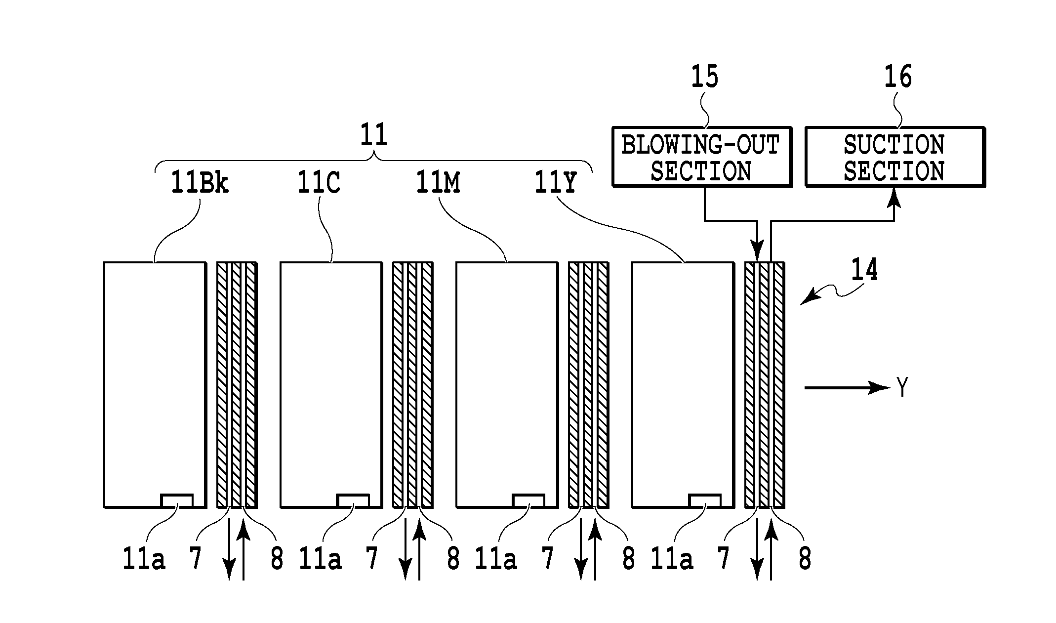
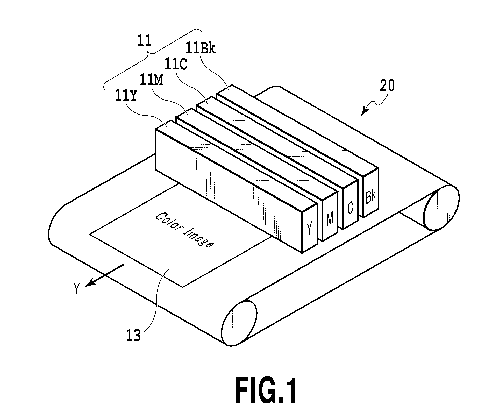
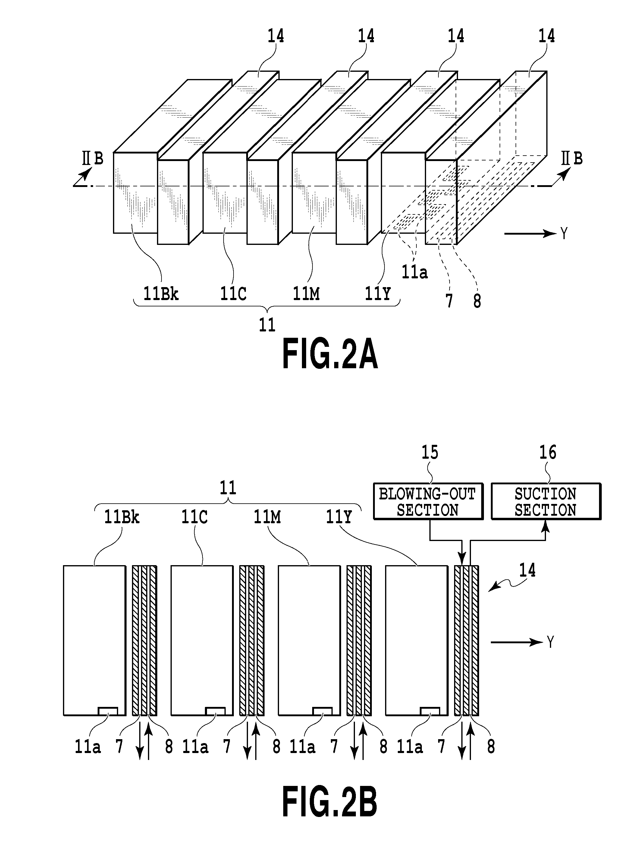
[0030]FIG. 1 is a schematic structural view of an inkjet printing apparatus as a liquid ejection apparatus of the present embodiment. The printing apparatus in this example is a printing apparatus constituting a so-called full-line type commercial printing apparatus. This printing apparatus uses, as a liquid ejection head (a print head) 11 for ejecting a liquid such as an ink, a long liquid ejection head (a line head) extending across the entire width of a printing area of a printing medium (a medium) 13. In this example, a liquid ejection head 11Y for ejecting a yellow ink, a liquid ejection head 11M for ejecting a magenta ink, a liquid ejection head 11C for ejecting a cyan ink, and a liquid ejection head 11Bk for ejecting a black ink are provided as the liquid ejection head 11. The printing medium 13 is conveyed in a direction of an arrow Y by a conveying mechanism 20 using a conveying belt, a conveying roller, and the like. In the liquid ejection head 11, a plurality of nozzles c...
second embodiment
[0041]The direction and angle of an inclination of a portion near an opening portion of the blowing-out opening 7 and the direction and angle of an inclination of a portion near an opening portion of the suction opening 8 are set in various ways as shown in FIGS. 6A, 6B, 6C, and 6D. More specifically, the direction of the gas blown out from the blowing-out opening 7 and the direction of the gas sucked into the suction opening 8 can be set at various angles relative to the surface of the gas blowing-out / suction mechanism 14 parallel to the ejection opening forming surface of the liquid ejection head 11 on which the ejection opening is formed. Further, the speed of the gas blown out from the blowing-out opening 7 and the speed of the gas sucked into the suction opening 8 do not need to be equal and preferably satisfy the condition of Formula (2). Further, a portion between the blowing-out opening 7 and the suction opening 8 does not need to be flat and may be concave or convex. In ord...
third embodiment
[0042]In the present embodiment, an electrode 18 is provided on a lower side (a back side) of the printing medium 13 facing the gas blowing-out / suction mechanism 14 as shown in FIGS. 7A and 7B. As stated above, in a case where gas is blown out from the blowing-out opening 7 and gas is sucked into the suction opening 8, most of the mist 12 can land on the printing medium 13. However, depending on conditions such as the amount of the blown-out gas q1, the amount of the sucked gas q2, the distance L (see FIG. 5), and the distance h (see FIG. 5), the mist 12 may flow downstream in the conveying direction of the arrow Y. The amount of the mist 12 flowing downstream can be kept small by providing the electrode 18 on the back side of the printing medium 13 facing the blowing-out / suction mechanism 14 as shown in FIGS. 7A and 7B.
[0043]Normally, the mist 12 is charged negatively. Accordingly, in a case where one electrode 18 is provided as shown in FIG. 7A, it is preferable to use a positive ...
PUM
 Abstract
Description
Claims
Application Information