Directional atomizer system for cleaning chandeliers

a technology for atomizer systems and chandeliers, which is applied in the direction of household cleaners, vacuum cleaners, tableware washing/rinsing machines, etc., can solve the problems of dissolved chemicals, dissolved chemicals, and dissolved chemicals, so as to eliminate the vacuum tube and suppress the splashing

Active Publication Date: 2011-12-22
INVENTIVE SOLUTIONS
View PDF27 Cites 6 Cited by
  • Summary
  • Abstract
  • Description
  • Claims
  • Application Information

AI Technical Summary

Benefits of technology

[0030]The bottom of the Quaff handle can be used to catch water and to dump it out when filled, thereby eliminating the vacuum tube when in tight spaces.
[0031]A plurality of upstanding bristles is formed on the cushioned pad. The bristles are operative to suppress splashing of water that impinges against the cushioned pad, to channel water impinging upon the cushioned pad to the at least one vacuum inlet, to remove at least one drop of water from a part being cleaned when the part is contacted by the bristles, and to cushion a fall of a part that lands atop the bristles.

Problems solved by technology

Conventional chandelier cleaning requires a labor-intensive, time-consuming dismantling of the chandelier and hand-washing of each part.
Floors and walls can still be marred by water as it splashes onto such tarps or drop cloths.
The water, which may contain dissolved chemicals, may also damage the floor simply by flowing off the tarp or drop cloths because such protective sheets have little or no water containment ability.
Complete saturation of the potting material by chemical sprays also weakens the bond and loosens such arms when there is no intention to change them.
These adhesives may or may not be weakened by chemical cleaning sprays.
However, clear epoxy may be softened and discolored over time by the application thereto of chemical sprays.
However, water and chemicals still pool in electrical junction boxes within the fixture and bowls that are common in chandeliers, thereby causing electrical shorts, corrosion, rusting, and other damage.
There are no prior art chandelier systems that use only hot water and pressure to clean the entire fixture.

Method used


Image

  • Directional atomizer system for cleaning chandeliers
  • Directional atomizer system for cleaning chandeliers
  • Directional atomizer system for cleaning chandeliers

Examples


Embodiment Construction

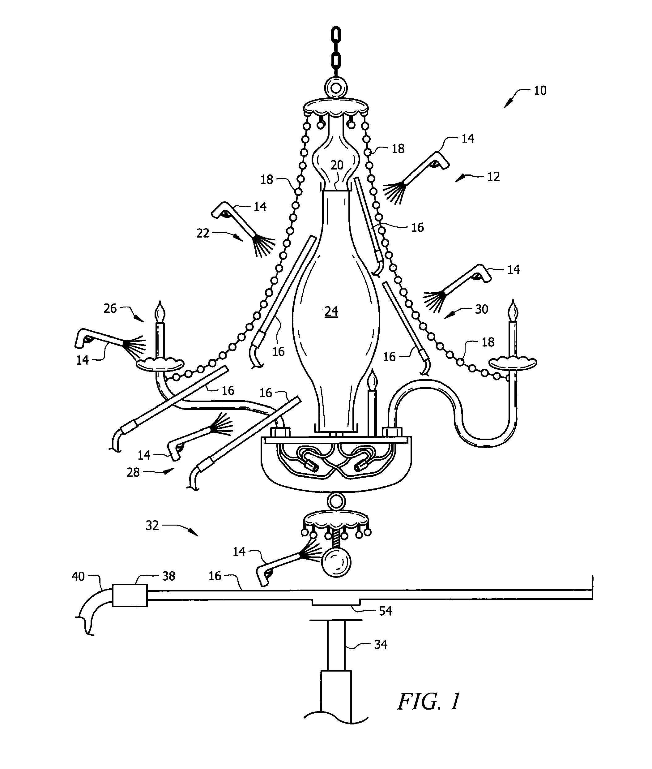
[0062]Referring now to FIG. 1, it will there be seen that a diagrammatic representation of a chandelier is denoted as a whole by the reference numeral 10.

[0063]FIG. 1 also includes six (6) examples of how the novel jet gun and vacuum shield may be used in cleaning various parts of chandelier 10.

[0064]As indicated by the reference numeral 12, novel jet gun 14 and novel vacuum shield 16 are positioned on opposite sides of a string of crystals 18 in the vicinity of check ring 20. Vacuum shield 16 is positioned in shielding relation to said check ring 20 so that water can not enter into said check ring and inside the center stem, thereby preventing pooling of water within said check ring as happens when prior art equipment and methods are used.

[0065]Reference numeral 22 indicates the respective positions of jet gun 14 and vacuum shield 16 when said shield is used to protect central part 24 of chandelier 10.

[0066]Reference numeral 26 indicates the respective positions of jet gun 14 and v...


PUM


Abstract

An apparatus for cleaning chandeliers includes a hand-held jet gun having a proximal end connected to a source of hot water under positive pressure and a distal end having a spray head for discharging hot water under pressure in a spray pattern. A hand-held vacuum shield has at least one vacuum inlet connected to a source of negative pressure. Hot water discharged from the spray head is attracted to the hand-held vacuum shield when the spray head and the hand-held vacuum shield are held in relatively close proximity to one another and the hand-held vacuum shield is in fluid communication with the source of negative pressure. An object disposed between the spray head and the hand-held vacuum shield is cleansed by the action of hot water under positive pressure impinging against it. The hand-held vacuum shield protects objects not disposed between the spray head and the hand-held vacuum shield.

Description

BACKGROUND OF THE INVENTION[0001]1. Field of the Invention[0002]This invention relates, generally, to the art of cleaning chandeliers or other structurally complex lighting fixtures. More particularly, it relates to a system that cleans lighting fixtures without chemicals and that protects the electrical parts of the fixture from water and chemicals.[0003]2. Description of the Prior Art[0004]Conventional chandelier cleaning requires a labor-intensive, time-consuming dismantling of the chandelier and hand-washing of each part.[0005]A major improvement in cleaning methods is disclosed in co-pending U.S. patent application Ser. No. 11 / 944,849, entitled “Method and Apparatus for Touchless Cleaning of a Chandelier” filed Dec. 17, 2007, by the present inventor. It discloses a tent-like structure that houses a chandelier so that it can be cleaned while still hanging from a ceiling. This substantially reduces the hours required to clean a chandelier. However, the electrical fixtures must be...

Claims


Application Information

Patent Timeline
Patent Type & Authority Applications(United States)
IPC IPC(8): A47L7/00
CPCA47L7/00A47L7/0095B08B3/04B08B17/00B08B3/026B08B11/02
Inventor CAMPBELL, KEITH S.
Owner INVENTIVE SOLUTIONS
Why Eureka
Try Eureka