Systems and methods of generating control signals

a technology of control signals and control signals, applied in the field of systems and methods of generating control signals, can solve problems such as remaining difficult to program lighting effects that are designed

Inactive Publication Date: 2007-06-12
SIGNIFY NORTH AMERICA CORP
View PDF267 Cites 266 Cited by
  • Summary
  • Abstract
  • Description
  • Claims
  • Application Information

AI Technical Summary

Benefits of technology

[0046]The present invention eliminates many of the problems associated with the prior art. An embodiment of the invention is a system for generating control signals. The system may allow a user to generate an image, representation of an image, algorithm or other effect information. The effect information may then be converted to lighting control signals to be saved or communicated to a networked lighting system. An embodiment of the invention may enable the authoring, generation and communication of control signals such that an effect is generated in a space or area.

Problems solved by technology

It remains difficult to program lighting effects that are designed to move through an area other than in a line or within a group of lighting systems.

Method used


Image

  • Systems and methods of generating control signals
  • Systems and methods of generating control signals
  • Systems and methods of generating control signals

Examples


Embodiment Construction

)

[0063]The description below pertains to several illustrative embodiments of the invention. Although many variations of the invention may be envisioned by one skilled in the art, such variations and improvements are intended to fall within the compass of this disclosure. Thus, the scope of the invention is not to be limited in any way by the disclosure below.

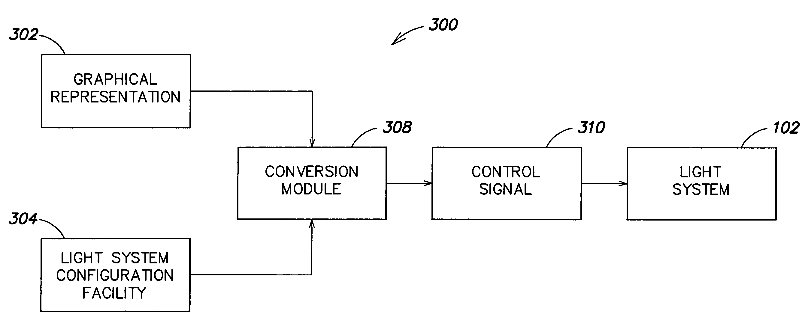
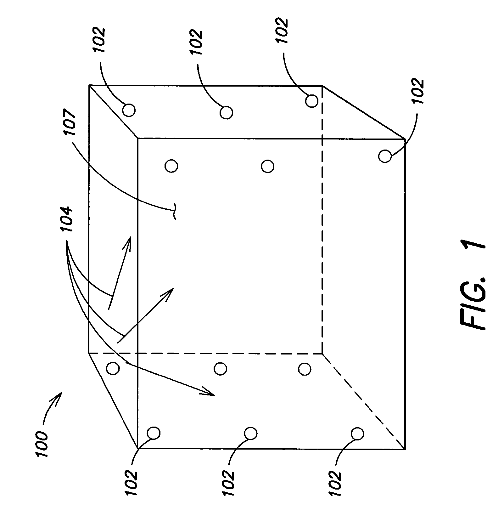
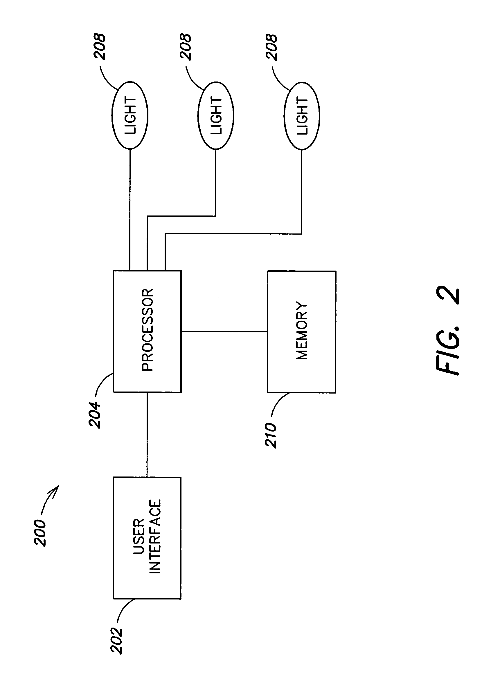
[0064]An embodiment of this invention relates to systems and methods for generating control signals. The control signals may be used to control a lighting system, lighting network, light, LED, LED lighting system, audio system, surround sound system, fog machine, rain machine, electromechanical system or other systems. Lighting systems like those described in U.S. Pat. Nos. 6,016,038, 6,150,774, and 6,166,496 illustrate some different types of lighting systems where control signals may be used.

[0065]To provide an overall understanding of the invention, certain illustrative embodiments will now be described, including various app...


PUM


Abstract

Separating a source in a stereo signal having a left channel and a right channel includes transforming the signal into a short-time transform domain; computing a short-time similarity measure between the left channel and the right channel; classifying portions of the signals having similar panning coefficients according to the short-time similarity measure; segregating a selected one of the classified portions of the signals corresponding to the source; and reconstructing the source from the selected portions of the signals.

Description

CROSS REFERENCE TO RELATED APPLICATIONS[0001]This patent application claims the benefit under 35 U.S.C. §119(e) of the following U.S. Provisional applications:[0002]Ser. No. 60 / 296,344, filed Jun. 6, 2001, entitled “Systems and Methods of Generating Control Signals”;[0003]Ser. No. 60 / 301,692, filed Jun. 28, 2001, entitled “Systems and Methods for Networking LED Lighting Systems”;[0004]Ser. No. 60 / 328,867, filed Oct. 12, 2001, entitled “Systems and Methods for Networking LED Lighting Systems;” and[0005]Ser. No. 60 / 341,476, filed Oct. 30, 2001, entitled “Systems and Methods for LED Lighting.”[0006]This application also claims the benefit under 35 U.S.C. §120 as a continuation-in-part (CIP) of U.S. Non-provisional application Ser. No. 09 / 971,367, filed Oct. 4, 2001, entitled “Multicolored LED Lighting Method and Apparatus,” now U.S. Pat. No. 6,788,011, which is a continuation of U.S. Non-provisional application Ser. No. 09 / 669,121, filed Sep. 25, 2000, entitled “Multicolored LED Lighti...

Claims


Application Information

Patent Timeline
Patent Type & Authority Patents(United States)
IPC IPC(8): G06K9/00
CPCH04S5/005H04S2400/15
Inventor DOWLING, KEVIN J.MORGAN, FREDERICK M.LYS, IHOR A.CHEMEL, BRIANBLACKWELL, MICHAEL K.WARWICK, JOHN
Owner SIGNIFY NORTH AMERICA CORP
Why Eureka
Try Eureka