Face imaging system for recordal and automated identity confirmation

a technology of face image and identity confirmation, which is applied in the field of face image recordal and identity confirmation, can solve the problems of slow image acquisition speed, poor image quality, and the need for human operation of such systems, and achieve the effect of rapid detection of face images and high quality

Inactive Publication Date: 2005-03-24
BIODENTITY SYST CORP
View PDF20 Cites 237 Cited by
  • Summary
  • Abstract
  • Description
  • Claims
  • Application Information

AI Technical Summary

Benefits of technology

An object of one aspect of the present invention is to overcome the above shortcomings by providing a face imaging system to rapidly detect face images of target persons within a security area and capture high quality images of those faces for recordal and / or for use in face recognition systems for purposes of face verification, face recognition, and face comparison.

Problems solved by technology

Some of the problems associated with using face recognition as a means of rapidly screening and identifying individuals attempting to gain access to a security area are the slow speed of image acquisition, the poor quality of the images acquired, and the need for human operation of such systems.
One of the main problems with such systems is that the video data is of low resolution and too “noisy” to provide consistently good results.
Widening the security area and / or trying to accommodate targets at varying distances to the camera, results in some targets having too little resolution in the video image to be properly analysed for accurate face recognition.
The main drawback of such systems, therefore, is that they operate successfully only over a very narrow angular and depth range.
Captured image quality and therefore the success of face recognition on those images is inconsistent.
The main drawback of these systems is that, as the distance from the first camera increases, it becomes difficult to recognize that a target within the field of view contains a face.
Second, the motorized pan, tilt and zoom functions of the second camera are relatively slow.
As a result, the system is only capable of tracking one person at a time.
The drawback of such systems is that they require the presence of an operator to detect and decide when to obtain the face images.
Such a system is typically so slow that not more than one person can be tracked at a time.
Such a system would severely restrict the flow of persons into the secure area, and in many cases, such as sports stadiums, would be totally unworkable.
Moreover, the system would still require an operator to ensure that the camera is pointed directly at the person's face, and do not include any means for ensuring that a proper pose is obtained.

Method used


Image

  • Face imaging system for recordal and automated identity confirmation
  • Face imaging system for recordal and automated identity confirmation
  • Face imaging system for recordal and automated identity confirmation

Examples


Embodiment Construction

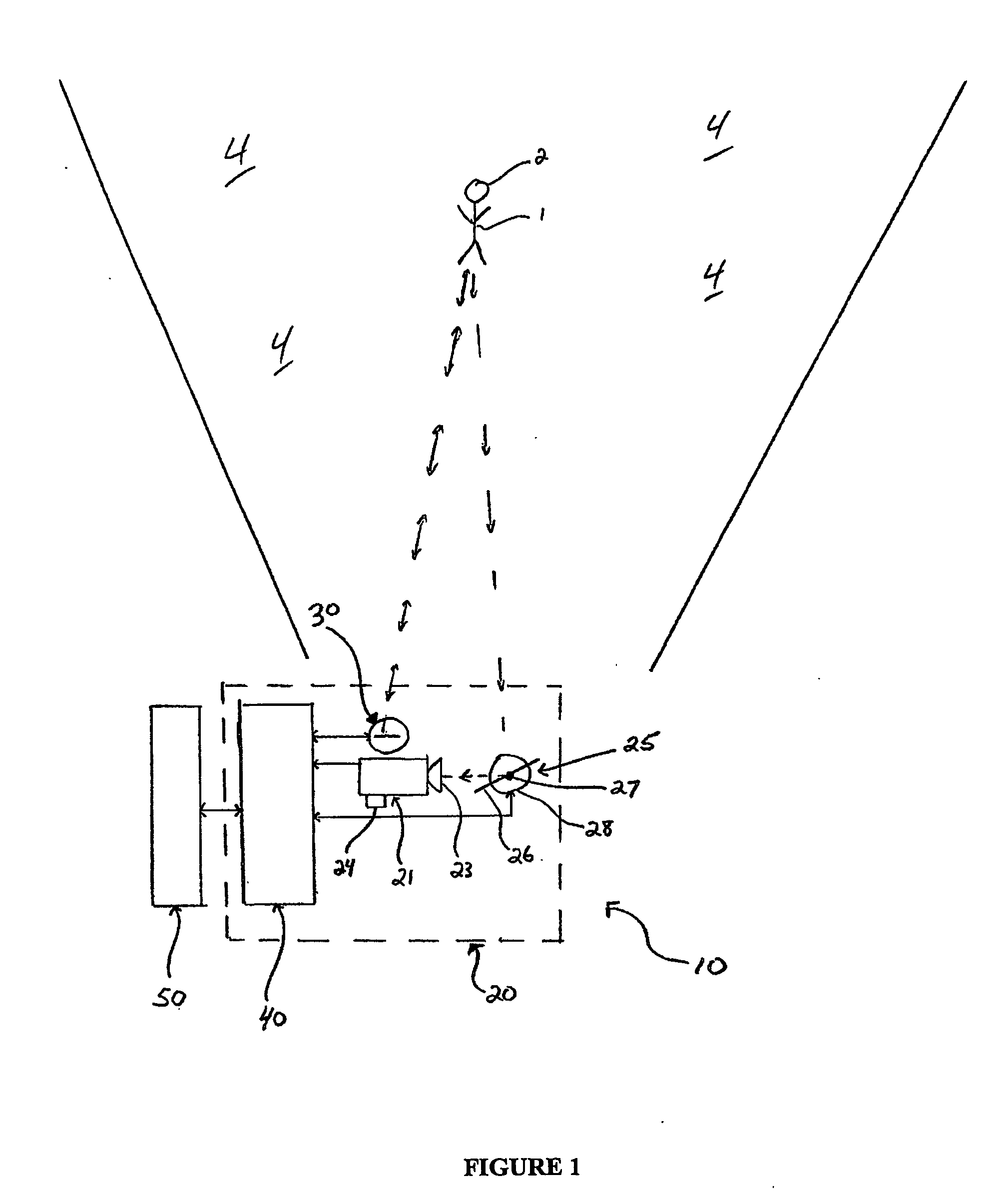
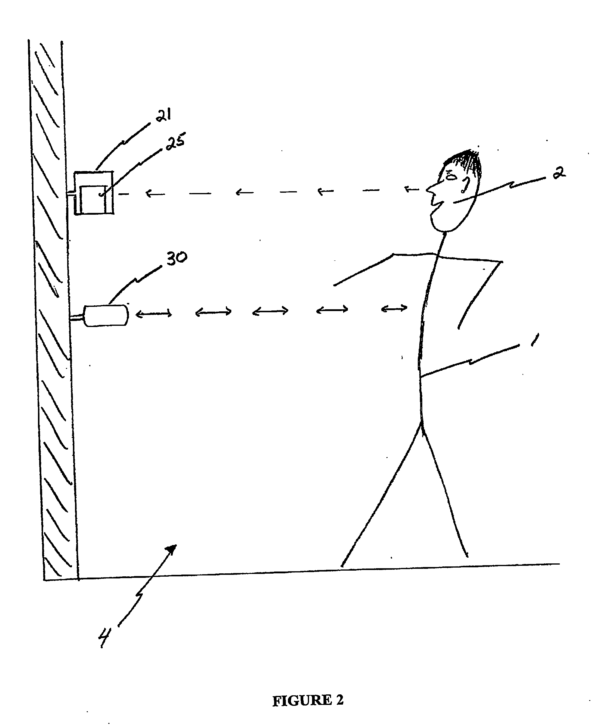
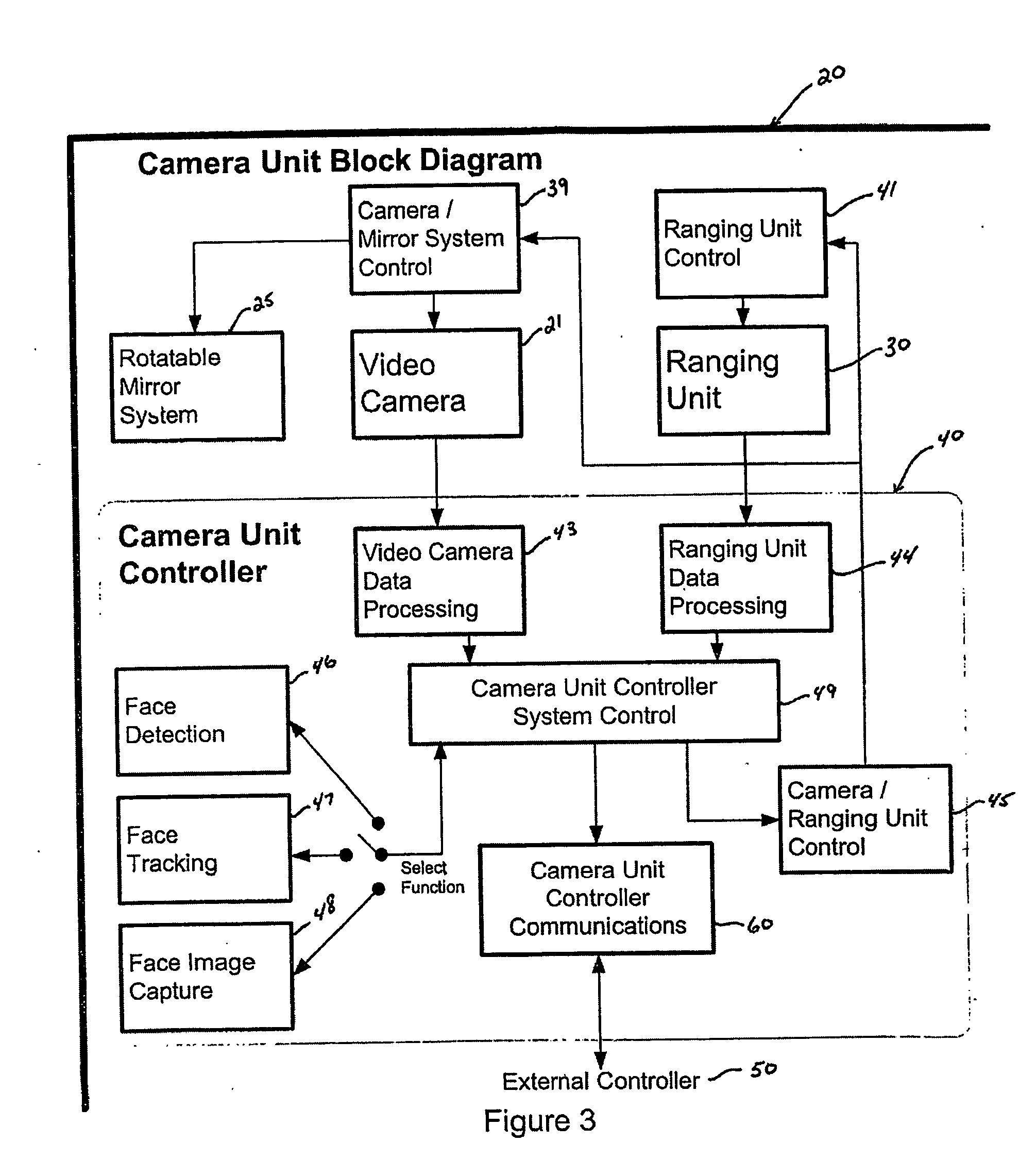
Referring to FIGS. 1 and 2, an automated identity confirmation system 10 is shown for monitoring targets 1 and obtaining images of target faces 2 entering a security area 4. As also shown in the architecture block diagram in FIG. 4, the automated identity confirmation system 10 comprises one or more camera units 20 and an external controller 50. The camera units 20 include a video camera 21, a rotatable mirror system 25, a ranging unit 30, and a camera unit controller 40.

It will be understood throughout this discussion that security area 4 is a three-dimensional space. The vertical direction is measured from the bottom to the top of the security area in the normal manner, while from the view point of camera unit 20, the horizontal direction is measured from side to side, and the depth is measured from camera unit 20 outward, also in the normal manner. Thus, for a person standing within security area 4 and facing camera unit 20, the vertical direction is from the person's feet to ...


PUM


Abstract

A face imaging system for recordal and/or automated identity confirmation, including a camera unit and a camera unit controller. The camera unit includes a video camera, a rotatable mirror system for directing images of the security area into the video camera, and a ranging unit for detecting the presence of a target and for providing target range data, comprising distance, angle and width information, to the camera unit controller. The camera unit controller includes software for detecting face images of the target, tracking of detected face images, and capture of high quality face images. A communication system is provided for sending the captured face images to an external controller for face verification, face recognition and database searching. Face detection and face tracking is performed using the combination of video images and range data and the captured face images are recorded and/or made available for face recognition and searching.

Description

FIELD OF THE INVENTION This invention relates to the field of face image recordal and identity confirmation using face images and in particular to the means by which faces can be recorded and identity can be confirmed using face images that are automatically obtained (i.e. without human intervention) in security areas where the movement of people cannot be constrained within defined boundaries. BACKGROUND OF THE INVENTION In a world where the prospect of terrorism is an ever increasing threat, there is a need to rapidly screen and record or identify individuals gaining access to certain restricted areas such as airports, sports stadiums, political conventions, legislative assemblies, corporate meetings, etc. There is also a need to screen and record or identify individuals gaining access to a country through its various ports of entry. One of the ways to identify such individuals is through biometric identification using face recognition techniques, which utilize various measureme...

Claims


Application Information

Patent Timeline
Patent Type & Authority Applications(United States)
IPC IPC(8): G06T1/00G06K9/00G07C9/00G08B15/00G08B25/00H04N7/18
CPCA61B5/0059A61B5/0062A61B5/107A61B5/1077A61B5/1176H04N7/186G07C9/00158G08B13/19608G08B13/1963G08B13/19689H04N7/181G06K9/00228G07C9/37G06V40/166G06V10/993
Inventor BEEK, GARY A . VANADLER, ANDREW JAMESCORDEA, MARIUS DANIELMOICA, SIMION ADRIANROSS, WILLIAM RSHAW, JOEL F
Owner BIODENTITY SYST CORP
Why Eureka
Try Eureka