High availability network security systems

a network security and high availability technology, applied in error detection/correction, program control, instruments, etc., can solve problems such as data security issues and loss of active connection state, and achieve the effect of high availability, faster detection of failures, and higher availability

Active Publication Date: 2007-03-27
JUMIPER NETWORKS INC
View PDF11 Cites 129 Cited by
  • Summary
  • Abstract
  • Description
  • Claims
  • Application Information

AI Technical Summary

Benefits of technology

[0015]The invention can be implemented to realize one or more of the following advantages. A cluster of redundant security devices can be used to achieve high availability. The cluster can be leaderless so that no one device is a single point of failure. The cluster can contain redundant paths and control interfaces for higher availability. Control messaging for the cluster can occur out-of-band from the production traffic.
[0016]A security device is provided that can self-detect its own failures and alert the rest of the cluster before stepping down from its role. The security device can also monitor the status of other devices for quicker detection of failures.
[0017]The security device can employ an active—active configuration to ...

Problems solved by technology

When public and private networks are linked, data security issues arise.
Also, conventional ...

Method used


Image

  • High availability network security systems
  • High availability network security systems
  • High availability network security systems

Examples


example 1

Firewall

[0079]FIG. 7 shows a security device in a firewall 700 that can exceed the 2 Gpbs threshold even during device failures, while also providing load balancing and stateful recovery.

[0080]The firewall 700 employs an active—active configuration. FIG. 7 shows four redundancy groups labeled virtual security devices (VSD) 1–4. Security devices 701 and 702 form a first mirror pair (redundancy group) and security devices 703 and 704 form a second mirror pair (redundancy group). Within each mirror pair, state information is exchanged and path monitors are used to monitor the redundant paths connecting the security devices.

[0081]The firewall 700 may act as one single firewall for a set of internal networks, or may act as a multi-customer managed firewall.

example 2

Security Gateway

[0082]FIG. 8 shows security device in a security gateway 800 that performs both firewall control and IP security virtual private network functions. Commonly-managed switches 803 may be used on both sides of the security devices 801, 802. The switches 803 can use an 802.1Q trunk in order to forward packets from different VLAN's between them for either of the devices 801, 802.

[0083]FIG. 8 depicts the security gateway 800 running in an Active / Active configuration and providing stateful recovery. More specifically, security device 801 is a master for VSD1 and a backup for VSD2. Similarly, security device 802 is a master for VSD2 and a backup for VSD1. The security devices may act as one security gateway for one set of internal networks, or may be employed to enable a multi-customer managed firewall and VPN solution.

example 3

Transparent Security Gateway

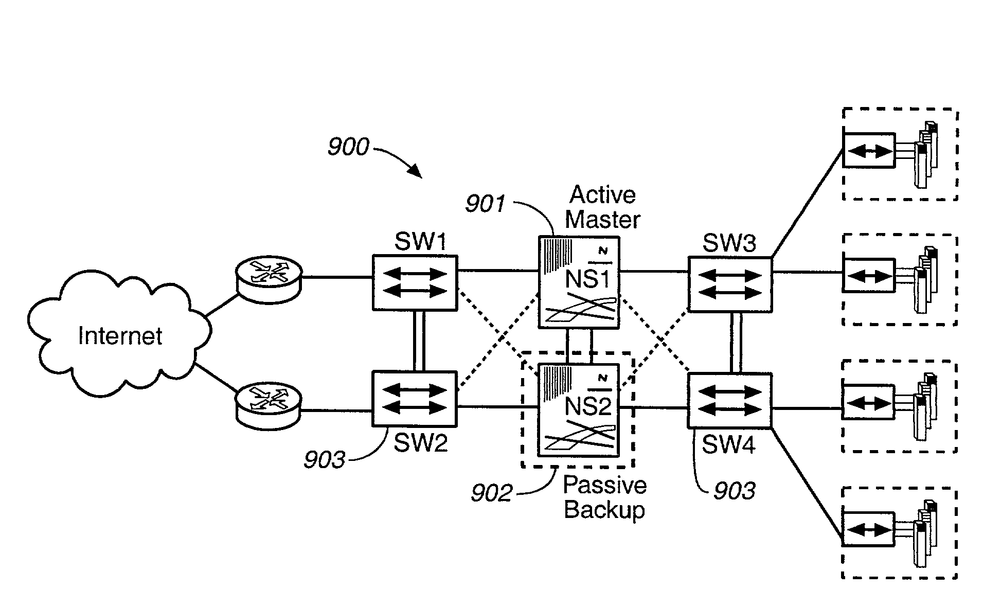
[0084]FIG. 9 shows a security device used in a transparent security gateway 900. A transparent security gateway is a security gateway that performs IP forwarding but does not perform address translation functions. The transparent security gateway 900 hides the existence of the security devices 901, 902 and simply acts like a securing bridge or a security bump in the wire. Common managed switches 903 may be used on both sides of the security devices 901, 902. The switches 903 have the capability to forward packets between them for either of the security devices 901, 902. The security devices 901, 902 can act as one security gateway for one set of internal networks. The security devices run in Active / Passive mode, though each will have its own primary IP and MAC addresses from which to perform IP Tracking. Security device 901 is the master, while security device 902 operates as a hot standby, remaining synchronized with all configurations and stateful updat...


PUM


Abstract

A system and method for a network security system are provided. The method includes providing a master device and a backup device within a cluster of network security devices, providing the backup device with state information for the master device, detecting failure in the cluster and using the state information to recover from the failure.

Description

BACKGROUND[0001]The present invention relates to network security systems and to redundancy protocols for network security systems.[0002]There are many emerging trends in the communications world, including the increase in network technology and the proliferation of data networks. One example of a data network is a packet switch communication system. A conventional packet switch communication system includes one or more routers connecting a plurality of users. A packet is the fundamental unit of transfer in the packet switch communication system. A user can be an individual user terminal or another network. A router is a switching device which receives packets containing data or control information on one port, and based on destination information contained within the packet, routes the packet out another port to the destination (or intermediary destination). Conventional routers perform this switching function by evaluating header information contained within the packet in order to...

Claims


Application Information

Patent Timeline
IPC IPC(8): G06F11/00
CPCG06F11/2035H04L45/586G06F11/2097H04L63/0272
Inventor LIU, CHANGMINGKE, YANCHEN, LINYANG, XIAOSONGLEBOVITZ, GREGORY M.
Owner JUMIPER NETWORKS INC
Why Eureka
Try Eureka