

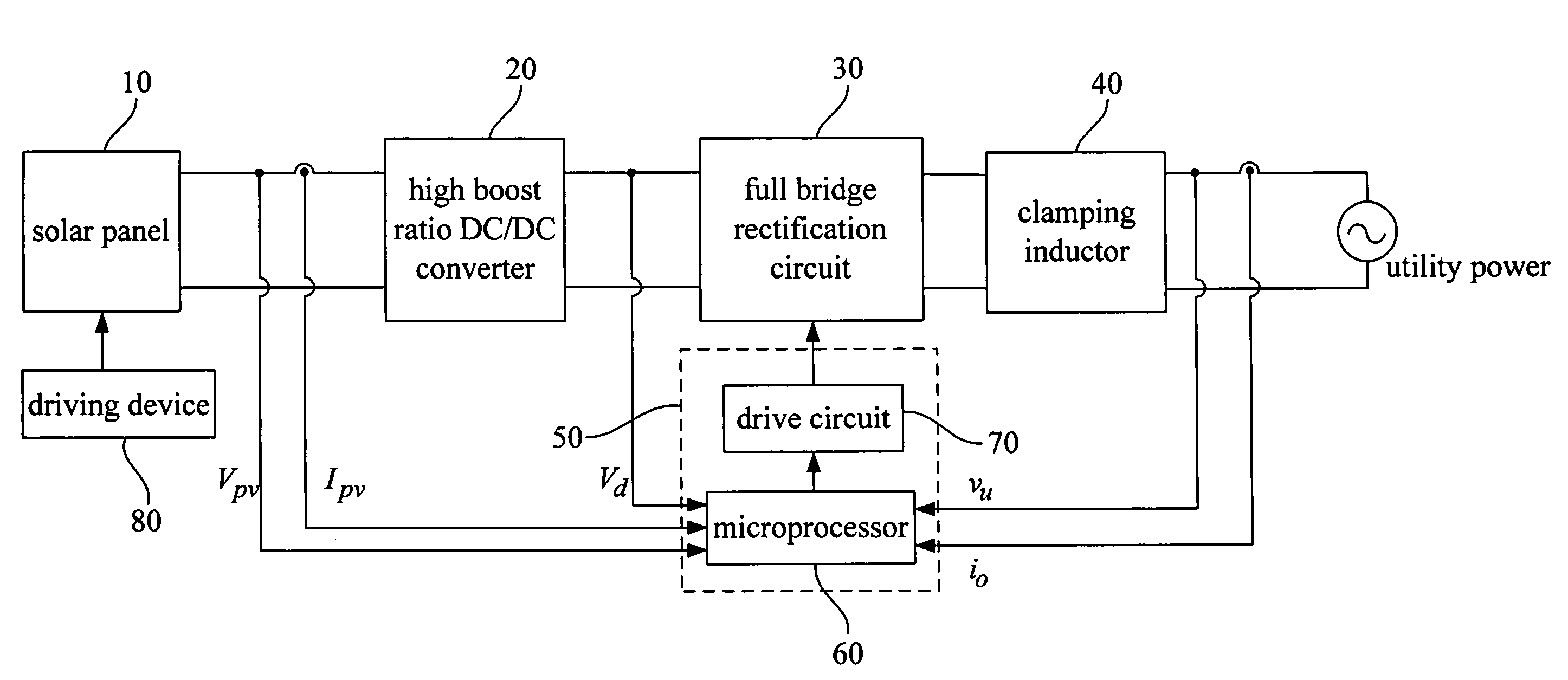
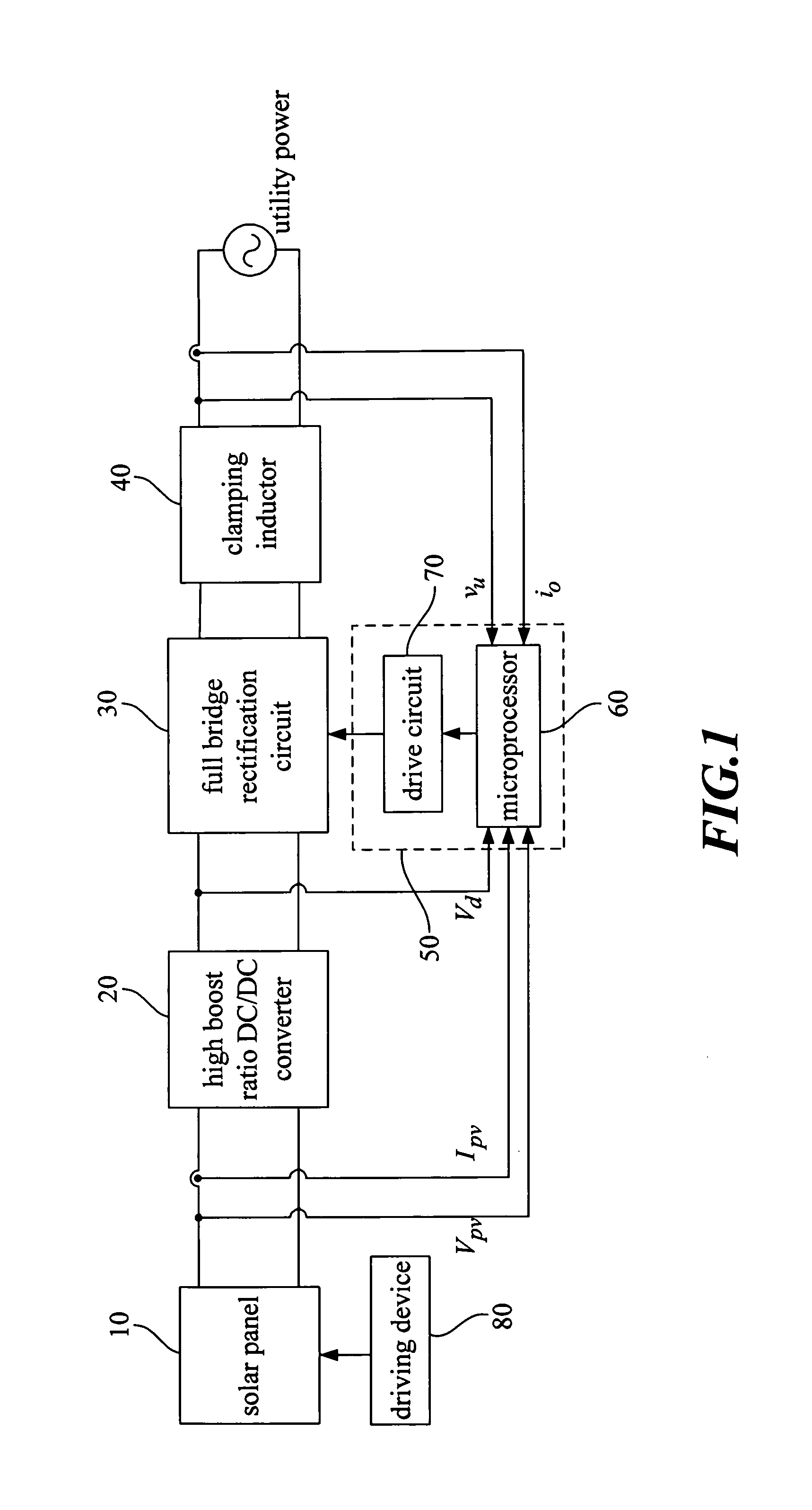
High-performance solar photovoltaic (PV) energy conversion system
a solar photovoltaic and energy conversion technology, applied in the direction of electric variable regulation, process and machine control, instruments, etc., can solve the problems of high price and energy crisis, easy to affect voltage, and inability to reuse energy, etc., to achieve stable dc voltage vd, simplify the design of the inverter control system, and high boost ratio dc/dc
- Summary
- Abstract
- Description
- Claims
- Application Information
AI Technical Summary
Benefits of technology
Problems solved by technology
Method used
Image

Examples
Embodiment Construction
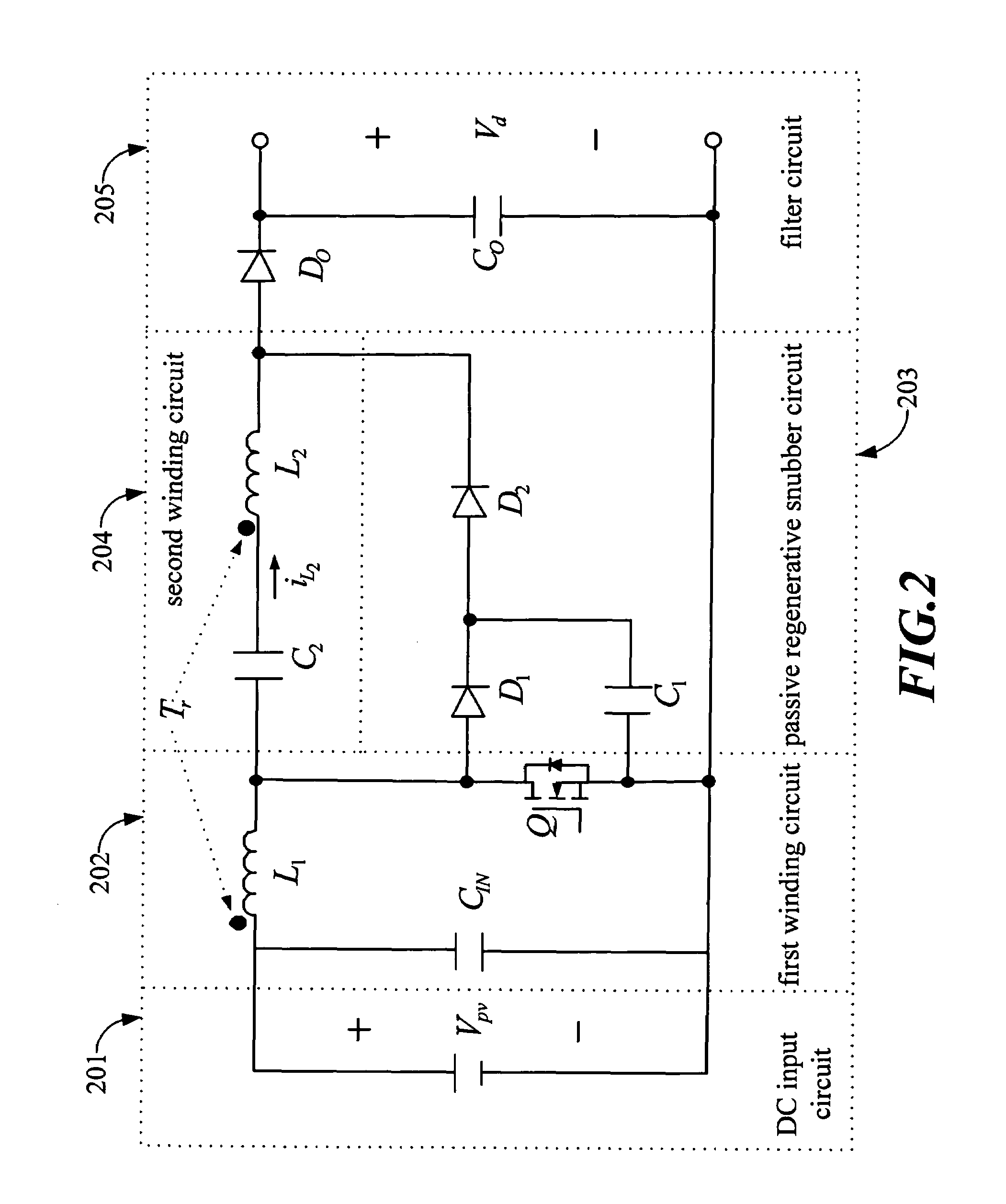
[0094]One of embodiment of the high performance solar energy conversion system of the present invention uses a plurality of 6 F-MSN-75W-R-02 solar panels connected in parallel to provide a low voltage DC to the high boost gain DC / DC conversion circuit; under the standard test condition (1 kW / m2, 25° C.), a single solar panel specified output power is 76.78 W, the specified output voltage is 17.228V, the specified output current is 4.4567 A, the open circuit voltage is 21.61V, the short circuit current is 4.9649 A and the photovoltaic conversion efficiency is 11.92%. Since the duty cycle of the switch Q of the high boost gain DC / DC conversion circuit is 0.5, the conducting currents of each circuit components have relative small harmonics, specially when the conduction switches are complementary components, the effect is more prominent. Also when the input voltage is around 17V the solar panel reaches a maximum power point and has near the optimum effectiveness, using equation (4) and...
PUM
 Abstract
Description
Claims
Application Information