Electrical junction box

A technology for electrical junction boxes and electrical components, applied in the direction of circuits, electrical components, circuits or fluid pipelines, etc., can solve the problems of large-scale electrical junction boxes, difficult to obtain space, heat generation, etc., to improve space efficiency and suppress water splashing , Effective heat dissipation effect

Inactive Publication Date: 2011-01-05
SUMITOMO WIRING SYST LTD
View PDF7 Cites 6 Cited by
  • Summary
  • Abstract
  • Description
  • Claims
  • Application Information

AI Technical Summary

Problems solved by technology

[0007] However, the above-mentioned electrical junction box requires an additional space for installing the drain groove in addition to the space for installing the electrical component mounting portion.
This will lead to the problem of increasing the size of the electrical junction box
[0008] In particular, in the case where the electrical junction box is provided with a plurality of electrical component mounting portions on the upper surface, it will be more difficult to obtain a space for disposing the drain groove, and will cause another problem: heat generation due to the plurality of electrical components question

Method used


Image

  • Electrical junction box
  • Electrical junction box
  • Electrical junction box

Examples


Embodiment Construction

[0024] Referring now to the drawings, an exemplary embodiment of an electrical junction box will be described below.

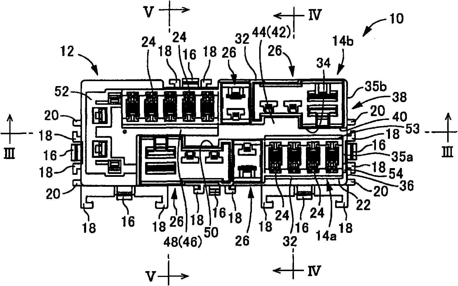
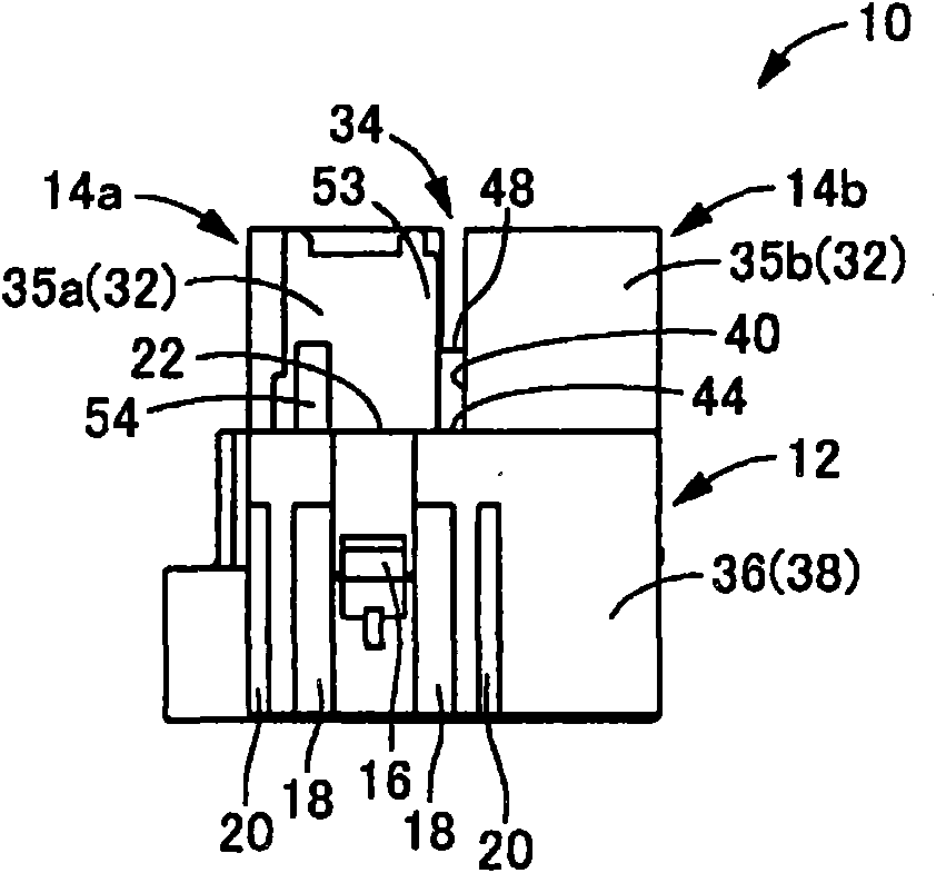
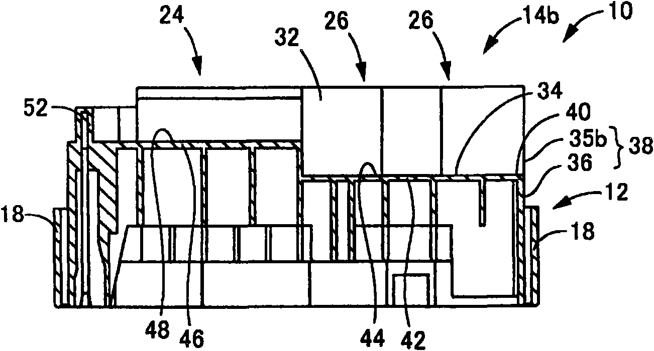
[0025] first, Figure 1-5 One embodiment of a fuse box 10 is shown, which is an example of an electrical junction box according to an exemplary embodiment. The fuse box 10 may be formed as a cuboid block made of synthetic resin. Specifically, the fuse box 10 may include a cuboid block-shaped main body 12 , a first electrical component mounting unit 14 a, and a second electrical component mounting unit 14 b. The first and second electrical component mounting portion units 14 a and 14 b protrude upward from the main body 12 .

[0026] The main body 12 may be provided with a plurality of locking pawls 16 at appropriate positions on the outer peripheral surface. On two opposite outer sides of each locking pawl 16, guide ribs 18 may be provided so that the guide ribs 18 are along the assembly direction of the cover 60 described later ( figure 2 in the up and d...


PUM


Abstract

To provide an electrical junction box having a new structure that includes a plurality of electrical component mounting sections that are open in an upper surface, such that (1) the structure is provided with a drainage groove for preventing accumulation of water without requiring any special space, and (2) the structure can eliminate a problem of heat generation from electrical components. An electrical junction box includes a first and second electrical component mounting section units. A plurality of electrical component mounting sections are arranged in straight lines to from the first and second units, respectively. The first and second electrical component mounting segment units are separated apart from each other by a given distance and are arranged in parallel with each other. A heat radiation drainage groove is provided between opposed portions of peripheral walls that constitute the adjacent first and second units. The heat radiation drainage groove is provided in at least one end with an end opening that extends to ends of the first and second units and is open in an outer peripheral surface.

Description

Background technique [0001] This application claims priority from Japanese Patent Application No. 2009-156376 filed in Japan on June 30, 2009, the entire disclosure of which is hereby incorporated by reference. [0002] Exemplary embodiments relate to an electrical junction box mounted on a motor vehicle or the like, and more particularly, to an electrical junction box provided with a plurality of electrical component mounting portions opened in a top surface. Background technique [0003] Hitherto, in order to improve the efficiency of wiring, electrical junction boxes have been installed in engine rooms and the like of motor vehicles. The electrical junction box houses current-carrying parts such as lead wires, bus bars or current-carrying plates as required, and houses various electrical parts such as relays, fuses, controls, for connecting external current-carrying circuits to internal current-carrying circuits connector. [0004] In the case where replaceable electric...

Claims


Application Information

Patent Timeline
Patent Type & Authority Applications(China)
IPC IPC(8): H02G3/16H02G3/08
CPCH01H85/47H01H2085/208H01H85/0026B60R16/0238H05K7/02
Inventor 江岛巧
Owner SUMITOMO WIRING SYST LTD
Why Eureka
Try Eureka