Liquid sealed vibration isolating device

a liquid sealing and vibration isolating technology, which is applied in the direction of shock absorbers, machine supports, mechanical equipment, etc., can solve the problems of reducing damping performance, affecting the working accuracy of relief valves, and not necessarily obtaining instantaneously enough relief amount, so as to prevent the generation of cavitation phenomenon, improve the working accuracy of relief valves, and accurate leakage

Active Publication Date: 2010-03-25
YAMASHITA RUBBER CO LTD +1
View PDF8 Cites 43 Cited by
  • Summary
  • Abstract
  • Description
  • Claims
  • Application Information

AI Technical Summary

Benefits of technology

[0027]According to the invention as defined in the sixth aspect, since the relief valve has a difference in rigidity in the circumferential direction, a low rigidity portion can be opened first by having the hydraulic liquid concentrated thereon to improve the working accuracy of the relief valve so as to obtain the accurate leakage.
[0028]According to the invention as defined in the seventh aspect, the thick wall portion is provided on the outer peripheral portion of the elastic diaphragm in the vicinity of the relief valve and supported by the frame member so as to arrest the rotation of the elastic diaphragm. Therefore, the elastic diaphragm provided with the relief valve on the outer peripheral side of the fixing portion is arrested the rotation thereof even in the severe conditions that the vibration of large amplitude is repeatedly inputted, so that the positional relationship between the relief valve and a leak passage can be kept constant, thereby making it possible to effectively prevent the generation of the cavitation phenomenon.
[0029]According to the invention as defined in the eighth aspect, since the thin relief valve and the thick wall portion are formed alternately in the circumferential direction, it is possible to give the difference in rigidity to the relief valve and improve the workability of the relief valve by this rigidity difference. The thick wall portion for creating the difference in rigidity can be used for arresting the rotation.
[0030]According to the invention as defined in the ninth aspect, since the thick wall portion having a higher rigidity is used for arresting the rotation, it is possible to materialize the more reliable rotation arresting structure.
[0031]According to the invention as defined in the tenth aspect, since the thick wall portion used for arresting the rotation is provided with the seal lip for adhering to the frame member, the liquid leakage can be effectively prevented.
[0032]According to the invention as defined in the eleventh aspect, since the projection projecting from the thick wall portion is fitted into a hole provided on the frame member so as to arrest the rotation, it is possible to materialize the rotation arresting structure without providing the thick wall portion of high rigidity in particular.

Problems solved by technology

Therefore, since the flow of the hydraulic liquid at the time of relief is throttled by a communication port of the orifice passage located on the side of the secondary liquid chamber, an enough relief amount may not necessarily by obtained instantaneously.
Then, the seal of the outer peripheral portion works incompletely to cause the leakage at the time of pressurization, so as to decrease the damping performance.

Method used


Image

  • Liquid sealed vibration isolating device
  • Liquid sealed vibration isolating device
  • Liquid sealed vibration isolating device

Examples


first embodiment

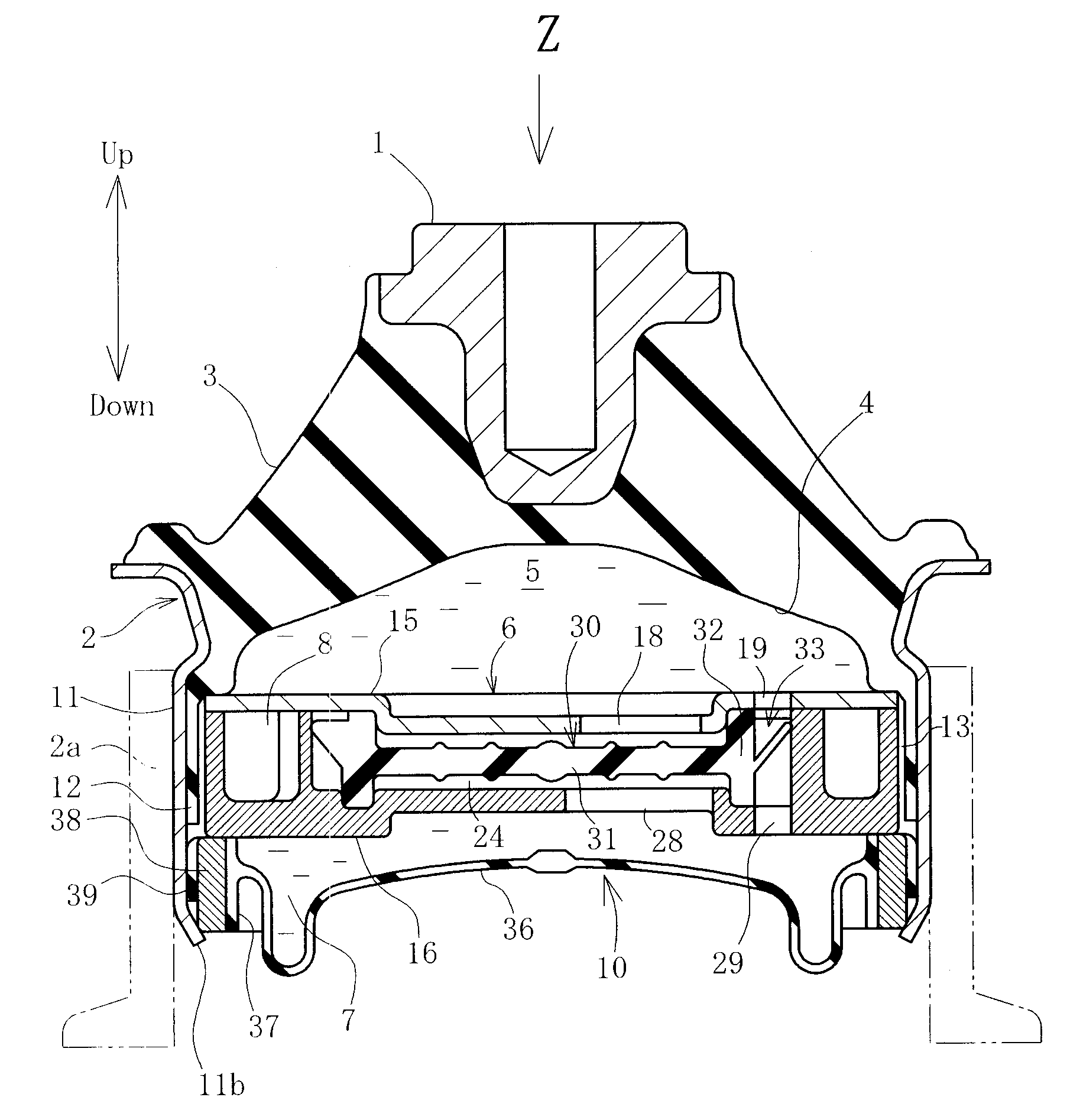
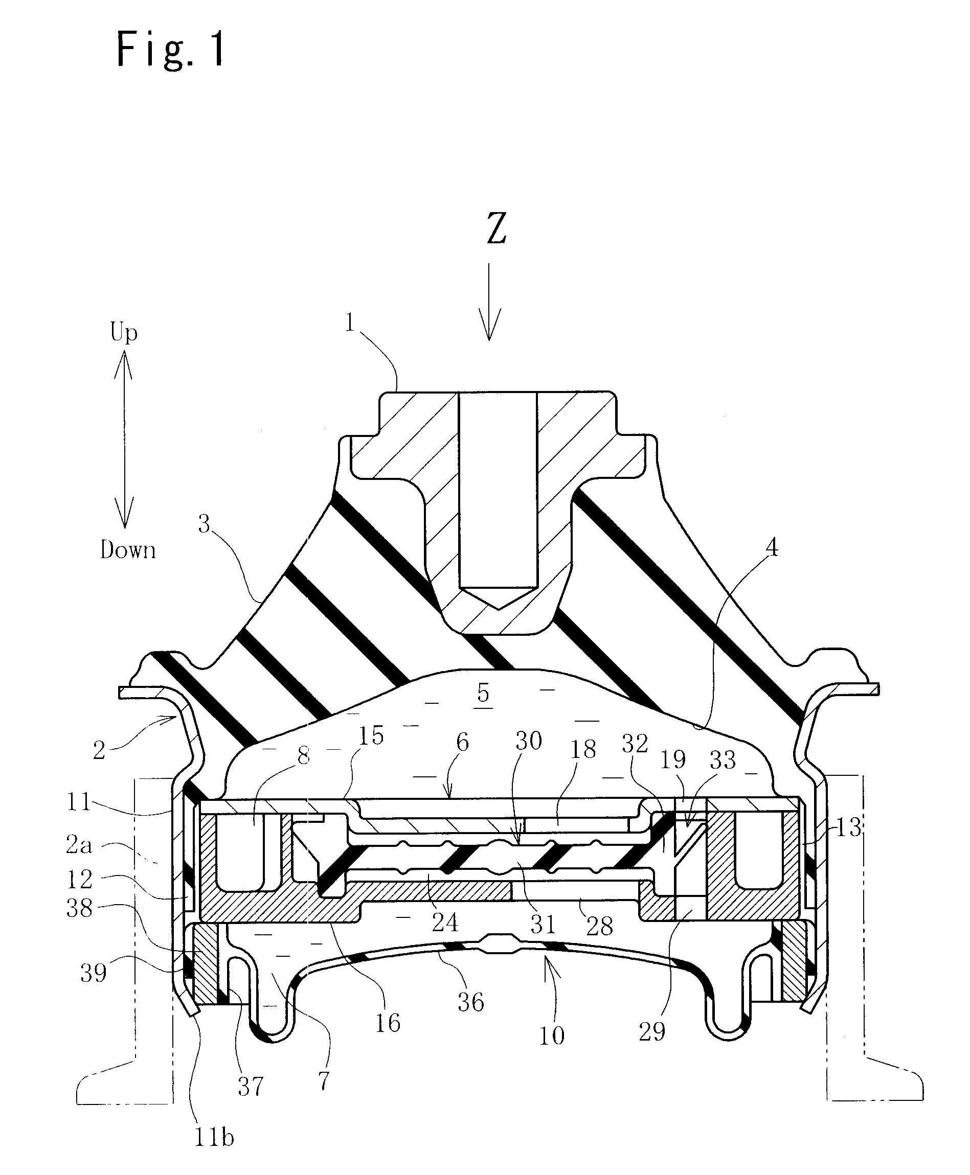
[0058]Hereinafter, the first embodiment embodied in an engine mount for motor vehicles will be explained with reference to the accompanying drawings, wherein FIG. 1 is a longitudinal cross sectional view of an engine mount, and FIG. 2 is an exploded view of each of components. FIG. 1 also is a cross section cut in the inputting direction Z of principal vibration. In the following explanation, each expression of the directions such as upward and downward, right and left is used based on an illustrated state in each of the drawings which is explained.

[0059]Referring now to these drawings, the engine mount comprises a first mounting member 1 to be mounted on the side of an engine (not shown) of the vibration source, a second mounting member 2 to be mounted on a vehicle body (not shown) on the vibration receiving side, and an insulator 3 adapted to connect these two members. The insulator 3 is formed by a known vibration isolating elastic member such as rubber or the like and is an elas...

second embodiment

[0083]FIG. 1, FIG. 2, FIG. 6, FIG. 7 and FIG. 9 to FIG. 21 concern the present invention. Herein, with respect to the structure similar to the previously described embodiments, like parts are given like reference characters and the explanation will be omitted (the same in each of the following embodiments).

[0084]In the following explanation, an upward and downward direction is expressed based on an illustrated state in FIG. 1 and a right and left direction is done based on an illustrated state in FIG. 9. Also, with respect to the structure similar to the previously described embodiment, like parts are given like reference characters and the explanation will be partially omitted.

[0085]Referring now to these drawings, the partition member 6 comprises the upper plate 15 and the lower holder 16 which are separated upwardly and downwardly. The elastic diaphragm 30 is held in a middle position between the upper plate 15 and the lower holder 16. The orifice passage 8 is provided radially o...

third embodiment

[0106]Next, the third embodiment will be explained with reference to FIG. 19 to FIG. 21. FIG. 19 is a plan view of the elastic diaphragm, FIG. 20 is a plan view showing the state of accommodating the elastic diaphragm in the lower holder, and FIG. 21 is a cross sectional view taken along line 21-O-21 of FIG. 20. As shown in these drawings, a single super thick wall portion 40 is provided in this embodiment. Also, as shown in FIG. 21, a groove 50 extending in the circumferential direction is provided on the upper wall of the super thick wall portion 40 so as to secure the interference when fixing by the upper plate 15. In this way, number of the super thick wall portion 40 is optional if it is one or more, and in all cases, the effect similar to the previous described embodiment can be obtained.

[0107]FIG. 22 is a plan view of the elastic diaphragm 30 according to the fourth embodiment. Although three super thick wall portions 40 are provided in this embodiment similar to the second e...


PUM


Abstract

To form a relief valve for preventing the generation of the cavitation phenomenon into a simple and accurately operable structure, there are provided a central thin wall portion and a fixing portion in an elastic diaphragm provided in the partition member to have the fixing portion fixed in position. A relief valve is integrally formed with an outer peripheral portion of the fixing portion. The relief valve is provided with an inclined surface formed on the side of a secondary liquid chamber and a recessed portion opened on the side of a primary liquid chamber and has a difference in rigidity in the circumferential direction. When the primary liquid chamber turns negative pressure, a hydraulic liquid in the secondary liquid chamber opens the relief valve and leaks to the primary liquid chamber so as to prevent the generation of the cavitation phenomenon.

Description

BACKGROUND OF THE INVENTION[0001]1. Field of the Invention[0002]The present invention relates to a liquid sealed vibration isolating device for use in an engine mount or the like for motor vehicles and more particularly, to the device capable of effectively reducing noises created due to a cavitation phenomenon.[0003]2. Description of the Related Art[0004]In the liquid sealed vibration isolating device of this kind, negative pressure is developed instantaneously in a primary liquid chamber when the heavy load is applied, so as to cause the cavitation phenomenon that hydraulic liquid is partially vaporized, and then the noise is generated. In view of this, there are proposed various kinds of devices for reducing transmission of the noise. As one of the proposed devices, there is known the art that in the case of where the primary liquid chamber turns the negative pressure, the primary liquid chamber and an orifice passage are short circuited to leak the hydraulic liquid (see a patent...

Claims


Application Information

Patent Timeline
Patent Type & Authority Applications(United States)
IPC IPC(8): F16F9/10
CPCF16F13/106
Inventor SAITO, JUNNISHIZAKA, MASATOMOKUBO, NOBUOYANAGASE, HIROSHI
Owner YAMASHITA RUBBER CO LTD
Why Eureka
Try Eureka