Robot controlling method, robot apparatus, program, recording medium, and method for manufacturing assembly component

a robot and control method technology, applied in the field of robot control methods, can solve the problems of low rigidity, deteriorating assembly work precision in some cases, and difficult to ensure that the vibrations of the leading end have converged, so as to improve the work efficiency improve the work precision of the articulated robo

Active Publication Date: 2015-12-17
CANON KK
View PDF28 Cites 20 Cited by
  • Summary
  • Abstract
  • Description
  • Claims
  • Application Information

AI Technical Summary

Benefits of technology

[0011]According to an aspect of the present invention, the position of the leading end of the articulated robot is obtained on the basis of the detection angles detected by the reduction gear-side angle detectors, and the time in which the position of the leading end of the articulated robot converges at the positioning completion position is set in the stopping duration of the articulated robot. Through this configuration, the vibrations of the articulated robot converge when the articulated robot is stopped for the set stopping duration, and thus the work precision of the articulated robot improves. Furthermore, it is not necessary to provide a large margin in the stopping duration to be set, and thus the stopping duration can be shorter than that in an existing technique, and the work efficiency of the articulated robot improves.

Problems solved by technology

The reduction gear that has low rigidity and is susceptible to vibration intervenes between the input side of the reduction gear and the leading end of the robot arm, and thus it is difficult to assure that the vibrations of the leading end have converged on the basis of the value at the input side of the reduction gear.
Therefore, there is a case in which the vibrations of the leading end of the robot arm have actually not converged, and the precision of assembly work deteriorates in some cases.

Method used


Image

  • Robot controlling method, robot apparatus, program, recording medium, and method for manufacturing assembly component
  • Robot controlling method, robot apparatus, program, recording medium, and method for manufacturing assembly component
  • Robot controlling method, robot apparatus, program, recording medium, and method for manufacturing assembly component

Examples


first exemplary embodiment

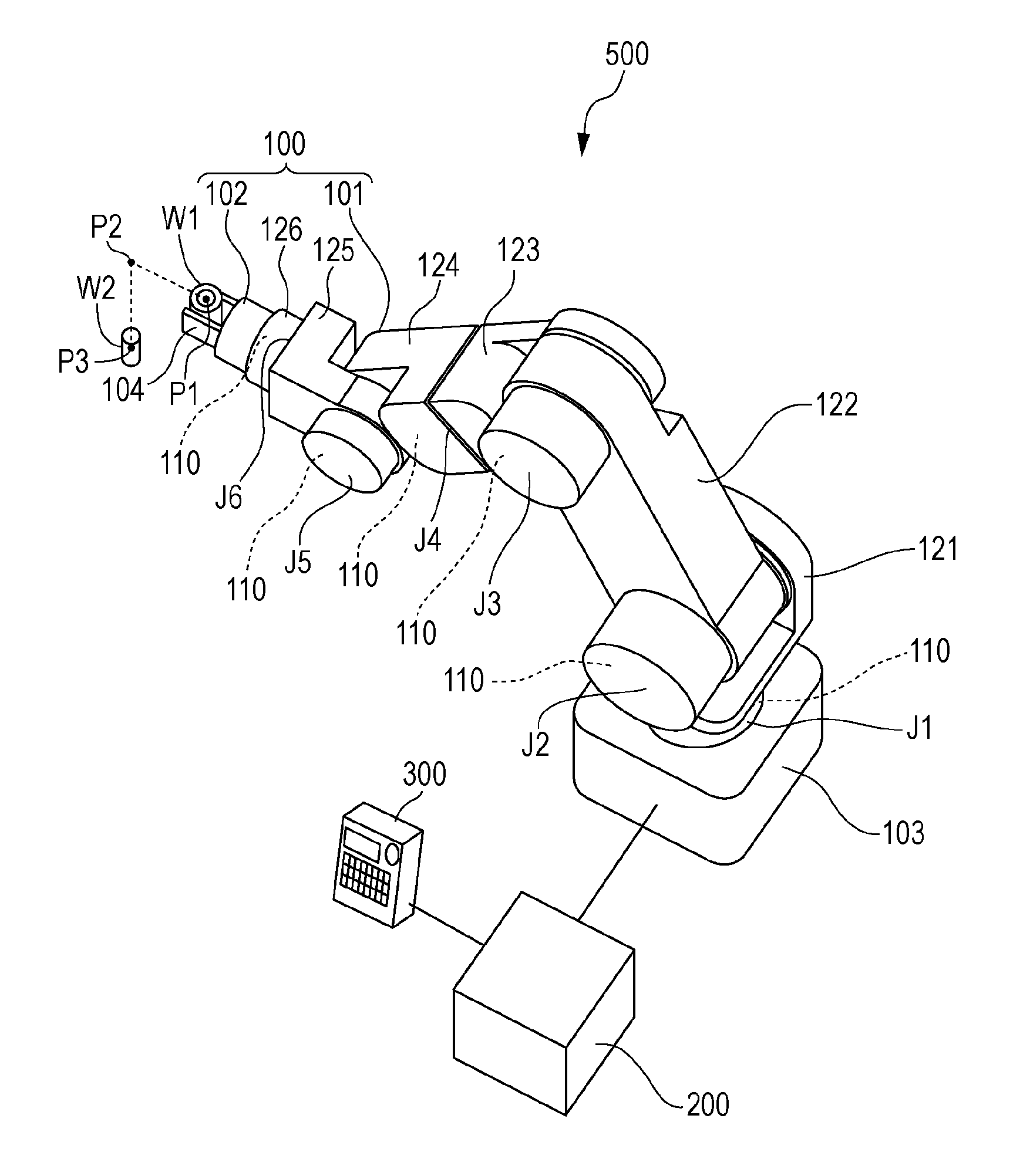
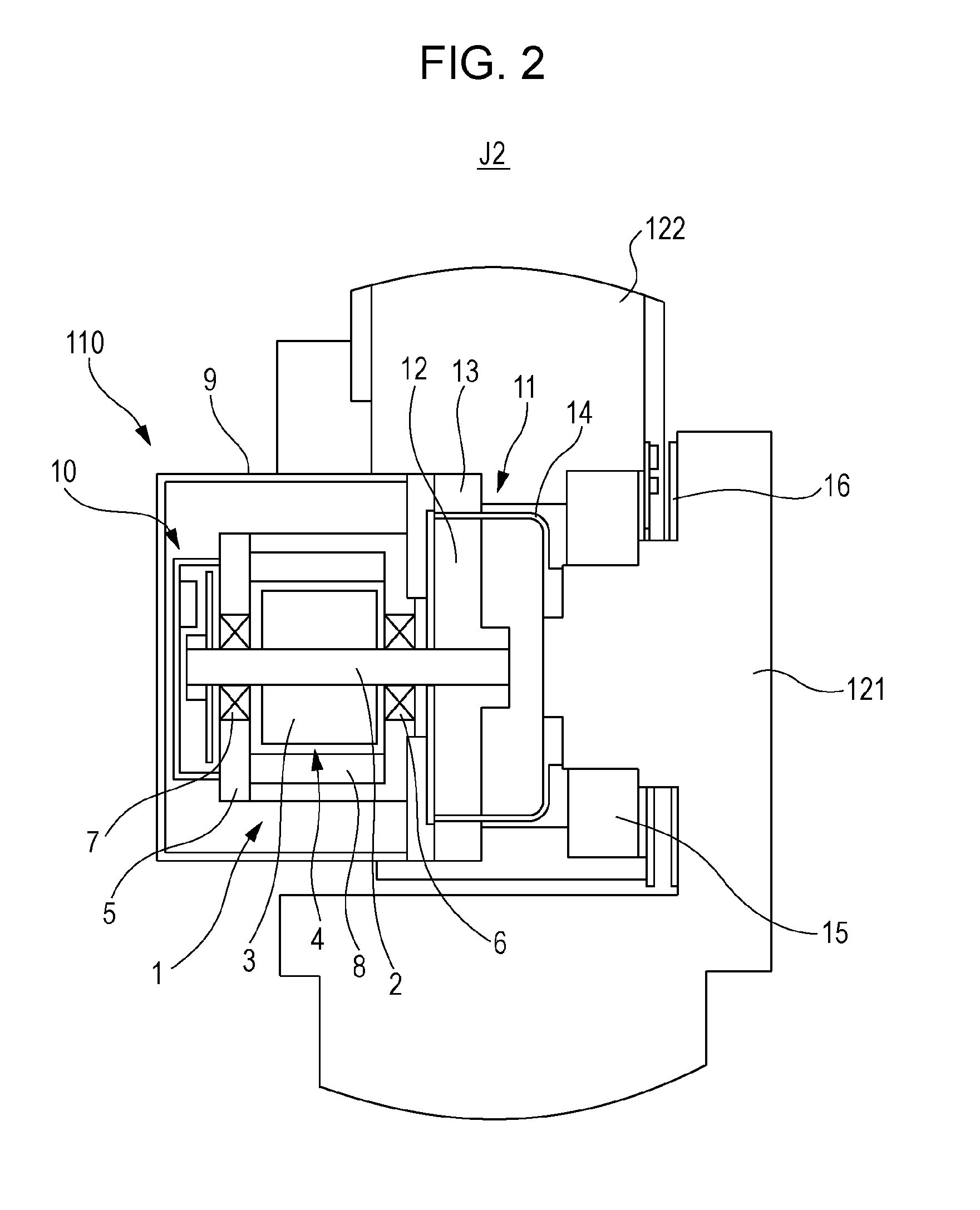
[0024]Hereinafter, a robot apparatus according to an exemplary embodiment of the present invention will be described. FIG. 1 is a perspective view illustrating a robot apparatus according to a first exemplary embodiment of the present invention.

[0025]A robot apparatus 500 illustrated in FIG. 1 is an industrial robot. The robot apparatus 500 includes a robot 100, a control device 200, and a teaching pendant 300. The robot 100 carries out assembly work in which the robot 100 assembles a first part W1, which is held by the robot 100, and a second part W2. The control device 200, which serves as a control unit, controls the robot 100. The teaching pendant 300 is connected to the control device 200.

[0026]The robot 100, which is an articulated robot, includes a vertically articulated robot arm 101 and a robot hand 102, which is an end effector, connected to the leading end of the robot arm 101.

[0027]A tool center point (TCP) is set at a leading end of the robot 100 (the leading end of the...

second exemplary embodiment

[0076]Subsequently, a robot controlling method for a robot apparatus according to a second exemplary embodiment of the present invention will be described with reference to FIGS. 7 and 8. FIG. 7 is a functional block diagram illustrating a control system of the robot apparatus according to the second exemplary embodiment of the present invention. FIG. 8 is a flowchart illustrating each of the steps in the robot controlling method implemented by a control device according to the second exemplary embodiment of the present invention. It is to be noted that the overall configuration of the robot apparatus according to the second exemplary embodiment is similar to the configuration of the robot apparatus 500 according to the first exemplary embodiment; thus, descriptions thereof will be omitted and the following description centers on points that differ from those of the first exemplary embodiment. The second exemplary embodiment differs from the first exemplary embodiment in terms of th...

third exemplary embodiment

[0095]Subsequently, a robot controlling method for a robot apparatus according to a third exemplary embodiment of the present invention will be described with reference to FIGS. 9 and 10. FIG. 9 is a functional block diagram illustrating a control system of the robot apparatus according to the third exemplary embodiment of the present invention. FIG. 10 is a flowchart illustrating each of the steps in the robot controlling method implemented by a control device according to the third exemplary embodiment of the present invention. It is to be noted that the overall configuration of the robot apparatus according to the third exemplary embodiment is similar to the configuration of the robot apparatus 500 according to the first exemplary embodiment; thus, descriptions thereof will be omitted and the following description centers on points that differ from those of the first exemplary embodiment. The third exemplary embodiment differs from the first exemplary embodiment in terms of the f...


PUM

PropertyMeasurementUnit
output angleaaaaaaaaaa
detection anglesaaaaaaaaaa
timeaaaaaaaaaa

Abstract

Feedback control is carried out on respective servomotors so that detection angles detected by respective input-side encoders become target angles to be obtained when a leading end of a robot has moved to a positioning completion position of a first motion. Subsequently, the position of the leading end of the robot is obtained on the basis of the detection angles detected by the respective output-side encoders. The time from a time point at which the detection angles detected by the input-side encoders are brought to the target angles through the feedback control to a time point at which a vibration width of the calculated position of the leading end of the robot relative to the positioning completion position converges within a convergence range is obtained. The obtained time is set in the stopping duration of the robot.

Description

BACKGROUND OF THE INVENTION[0001]1. Field of the Invention[0002]The present invention relates to robot controlling methods for controlling articulated robots, robot apparatuses, programs, recording media, and methods for manufacturing assembly components.[0003]2. Description of the Related Art[0004]Conventionally, various types of robot apparatuses are used in factories and so on, and nowadays, in order to carry out more complex operations than before, robot apparatuses that include multiaxial, articulated robots are widely used.[0005]When an articulated robot is used as a production apparatus, the robot needs to operate at high speed in order to increase the work efficiency. Accordingly, it is necessary to determine, as soon as possible, that one motion has certainly completed, or in other words, that positioning has completed.[0006]With respect to how the completion of positioning of a robot is to be determined, to date, a following technique has been proposed. For example, the po...

Claims


Application Information

Patent Timeline
Patent Type & Authority Applications(United States)
IPC IPC(8): B25J9/16B23P19/04B25J9/02
CPCB25J9/1687B25J9/02B25J9/1674B23P19/04Y10T29/49828Y10S901/23Y10S901/25Y10T74/20317Y10S901/09G05B2219/34388G05B2219/37297G05B2219/39098
Inventor ISHIKAWA, TAKAHIROOSAKA, TSUTOMUKAWAMURA, SHUNSUKE
Owner CANON KK
Why Eureka
Try Eureka