
Method for balloon-aided vertebral augmentation

a technology of bone structure and balloon, which is applied in the field of methods for stabilizing bone structure, can solve the problems of increasing the “height” of the bone, affecting the long bones, and affecting the health of the patient, so as to facilitate the bone augmentation, strengthen the bone structure, and restore the height of the bon

Active Publication Date: 2014-02-13
STRYKER CORP
View PDF2 Cites 12 Cited by
  • Summary
  • Abstract
  • Description
  • Claims
  • Application Information

AI Technical Summary

Benefits of technology

The patent describes a method of using a balloon to help restore the height of a damaged bone and reinforce it using a process called vertebroplasty. A pre-curved device is used to target the area of the bone that needs treatment. An expandable member is then inflated using the balloon to create cavities in the bone where the material used to restore bone height and strength can be placed. Overall, this method allows for a more targeted and effective treatment of bone damage.

Problems solved by technology

The damage associated with these conditions may also affect long bones, the pelvis, and other bones.
This action, in turn, compresses cancellous bone and other tissue to form a cavity, and may also cause a “height” of the bone to increase.

Method used


Image

  • Method for balloon-aided vertebral augmentation
  • Method for balloon-aided vertebral augmentation
  • Method for balloon-aided vertebral augmentation

Examples


Embodiment Construction

[0020]Embodiments are described with reference to the drawings in which like elements generally are referred to by like numerals. The relationship and functioning of the various elements of the embodiments may better be understood by reference to the following detailed description. However, embodiments are not limited to those illustrated in the drawings. It should be understood that the drawings are not necessarily to scale, and in certain instances details may have been omitted that are not necessary for an understanding of embodiments disclosed herein, such as—for example—conventional fabrication and assembly.

[0021]Various embodiments will be described more fully hereinafter. The invention is defined by the claims, may be embodied in many different forms, and should not be construed as limited to the embodiments set forth herein; rather, these embodiments are provided so that this disclosure will be thorough and complete, and will fully convey enabling disclosure to those skilled...


PUM


Abstract

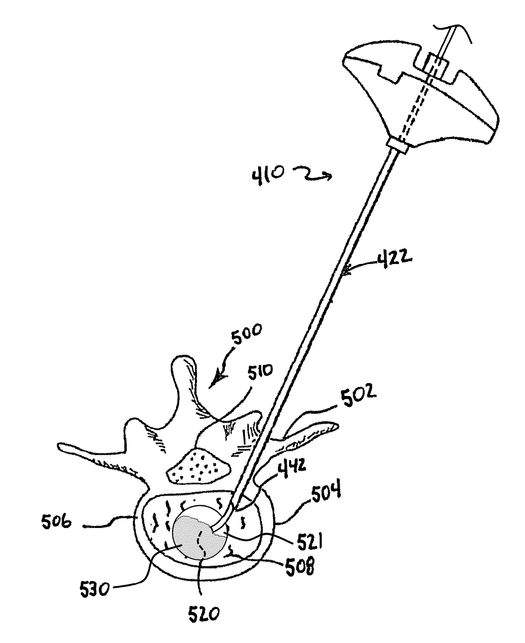
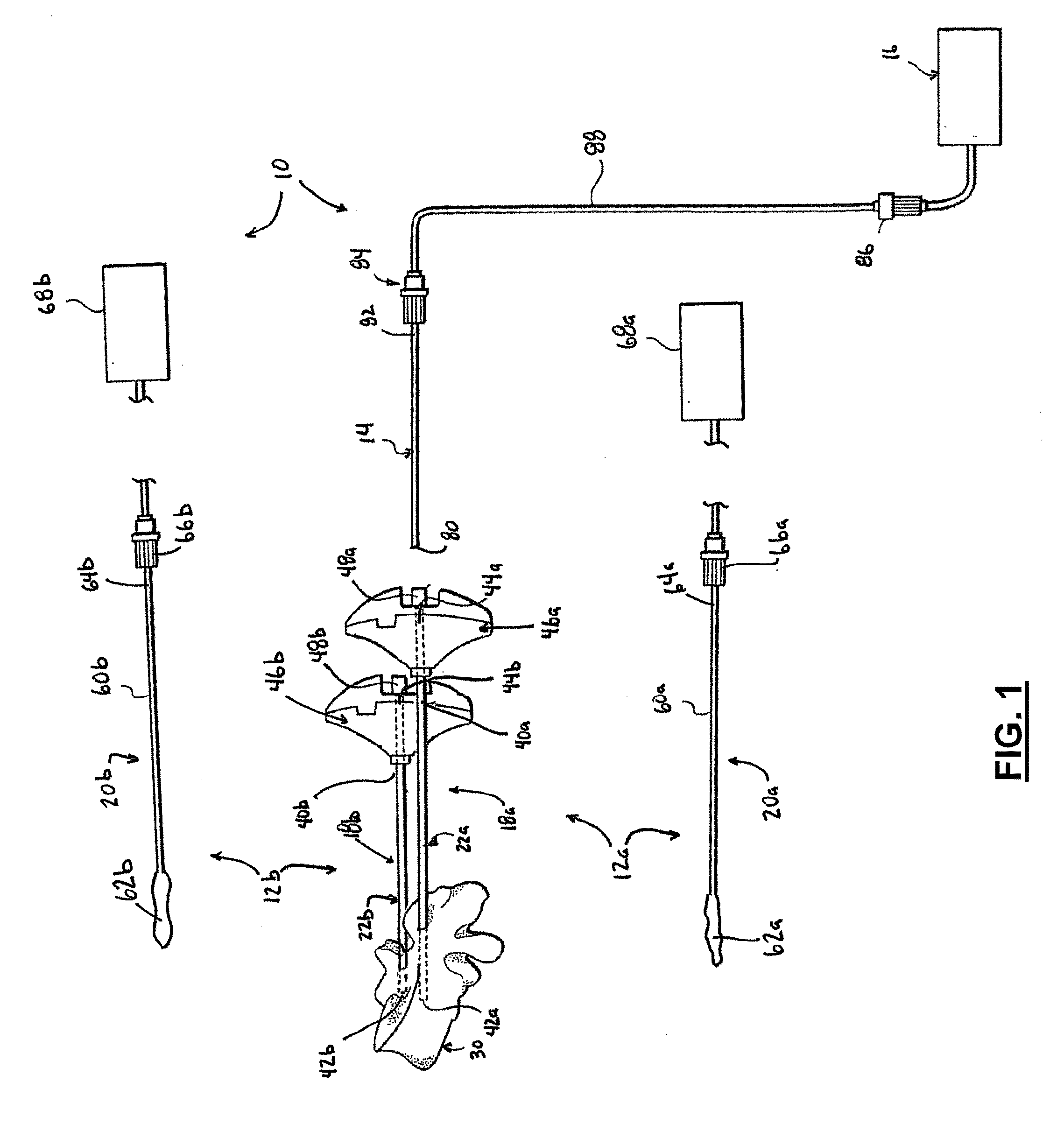
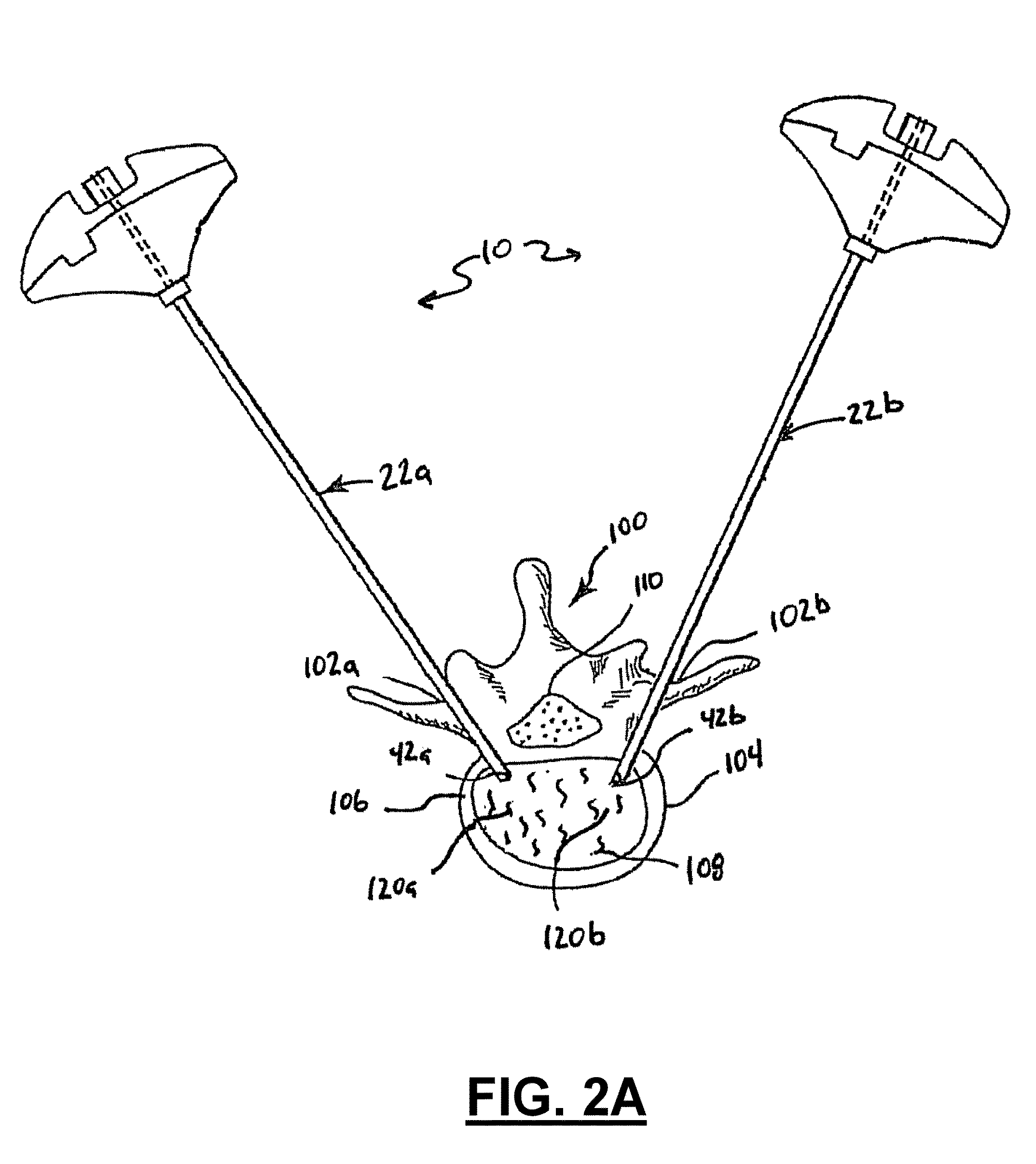
An expandable member bone augmentation system and single-access-point methods for bone augmentation using same are provided. In certain embodiments, a pre-curved stylet with an overlying delivery tube may be used to target an approximately centered target site within a bone structure, facilitating direction thereto of an expandable member useful for creating a cavity that may receive curable material to restore bone height and / or to reinforce the bone structure. An expandable member such as, for example, a balloon can be used to create a plurality of voids by displacing bone material, where the voids can be filled with curable material to augment the bone.

Description

CROSS-REFERENCE TO RELATED APPLICATIONS[0001]This application is a continuation-in-part of co-pending, co-owned U.S. patent application Ser. No. 13 / 483,919, filed May 30, 2012, which is incorporated by reference herein in its entirety.TECHNICAL FIELD[0002]Embodiments disclosed herein generally relate to methods for stabilizing bone structures. More particularly, they relate to systems and methods for stabilizing and restoring the height of a bone structure such as, for example, a vertebral body.BACKGROUND[0003]Surgical intervention of damaged or compromised bone sites has proven highly beneficial for patients, including, for example, patients with back pain associated with vertebral damage. The vertebral damage may be due to injury and / or a degenerative condition such as, for example, aging and / or osteoporosis. The damage associated with these conditions may also affect long bones, the pelvis, and other bones.[0004]Bones of the human skeletal system include mineralized tissue that m...

Claims


Application Information

Patent Timeline
Patent Type & Authority Applications(United States)
IPC IPC(8): A61B17/88
CPCA61B17/8822A61B17/1642A61B17/8805A61B17/8811A61B17/8855A61B2017/00867A61B2090/062A61B2090/0811A61B2090/3966
Inventor SCHAUS, ERIN L.KRUEGER, JOHN A.LINDERMAN, EVAN D.
Owner STRYKER CORP
Learn More