Robot, robot control device, and robot system

a robot control and robot technology, applied in the field of robots, can solve the problems of increased cost, insufficient suppression of vibration, and easy performance of more complex motions, and achieve the effect of easy and reliably suppressing vibration

Active Publication Date: 2014-03-06
SEIKO EPSON CORP
View PDF4 Cites 15 Cited by
  • Summary
  • Abstract
  • Description
  • Claims
  • Application Information

AI Technical Summary

Benefits of technology

[0008]An advantage of some aspects of the invention is to provide a robot that can

Problems solved by technology

Because of this, complex and massive arithmetic processing is needed, and a control device having a high-performance and expensive CPU (Central Processing Unit) or the like is needed, leading to a problem of increased cost.
Moreover, since c

Method used


Image

  • Robot, robot control device, and robot system
  • Robot, robot control device, and robot system
  • Robot, robot control device, and robot system

Examples


Embodiment Construction

[0067]Hereinafter, a robot, a robot control device, and a robot system of the invention will be described in detail based on a preferred embodiment shown in the accompanying drawings.

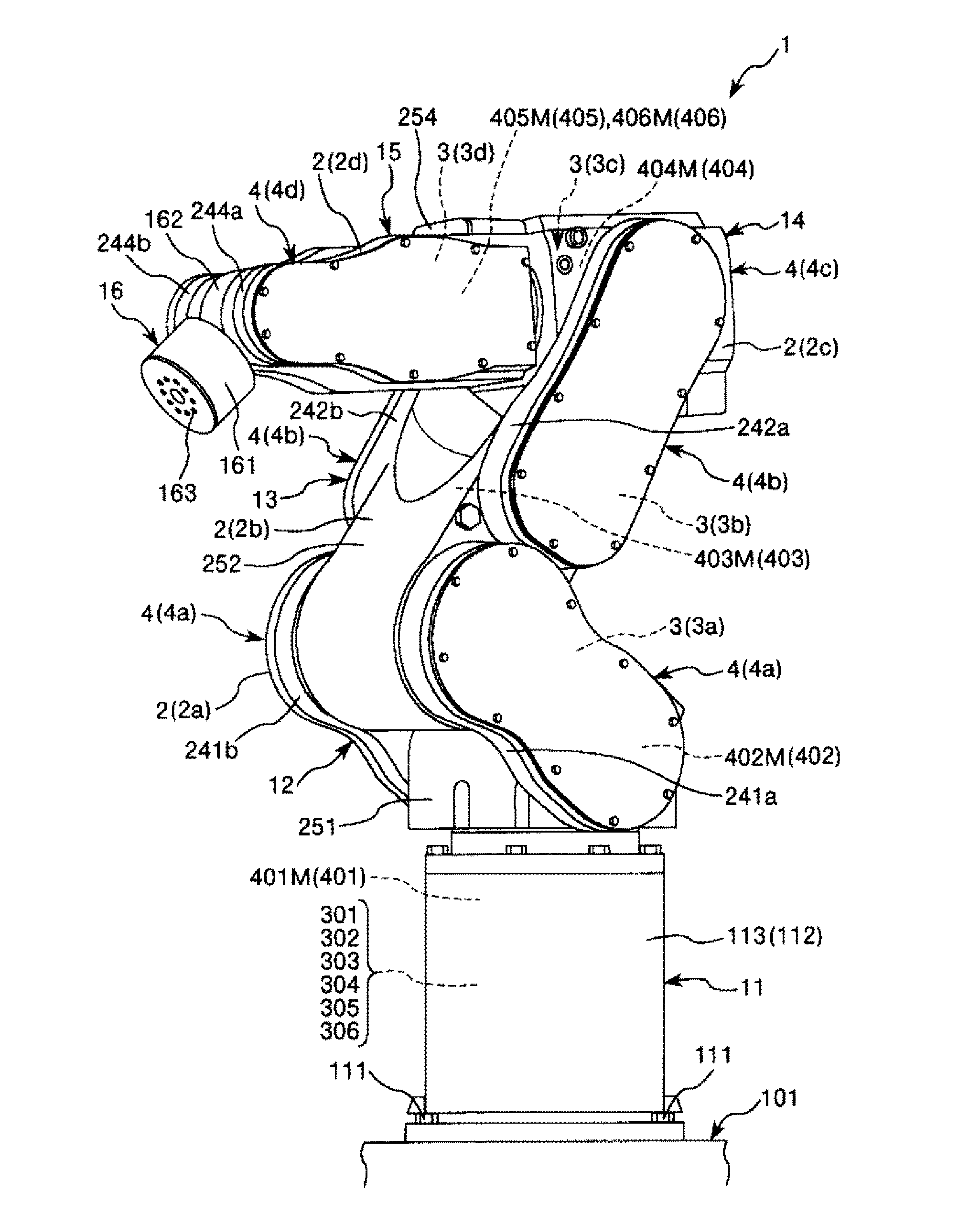
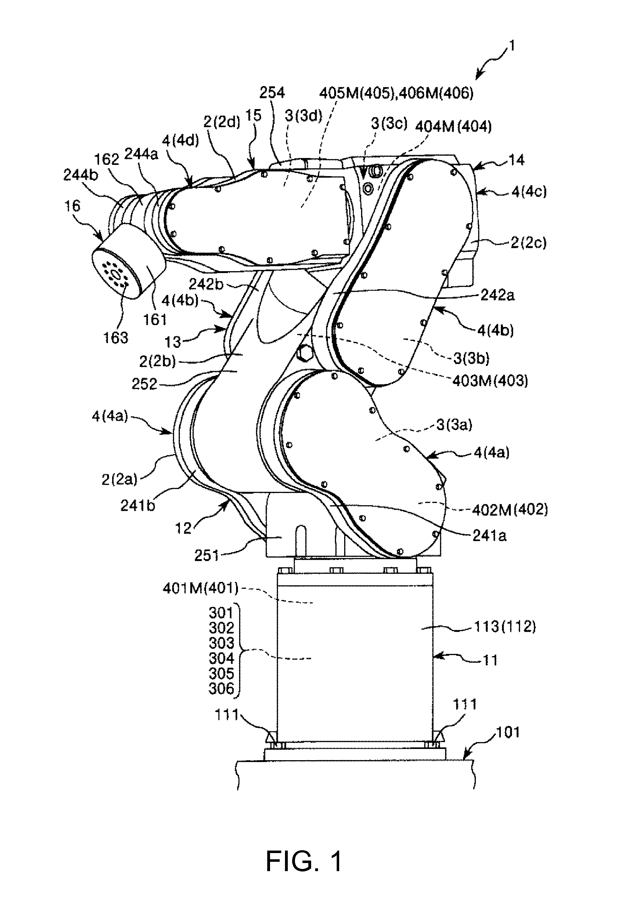
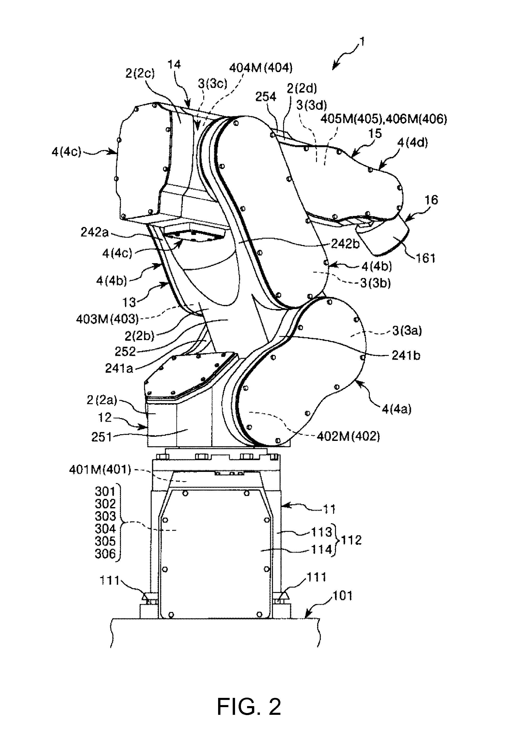
[0068]FIG. 1 is a perspective view of the embodiment of the robot of the invention as viewed from the front side. FIG. 2 is a perspective view of the robot shown in FIG. 1 as viewed from the back side. FIG. 3 is a schematic view of the robot shown in FIG. 1. FIG. 4 is a block diagram of a main portion of the robot system having the robot shown in FIG. 1. FIG. 5 is an elevation view of the robot shown in FIG. 1. FIG. 6 shows the vicinity of a first angular velocity sensor in a first arm of the robot shown in FIG. 1. FIG. 7 shows the vicinity of a second angular velocity sensor in a third arm of the robot shown in FIG. 1. FIG. 8 is a cross-sectional view of a first angular velocity sensor unit of the robot shown in FIG. 1. FIGS. 9 to 13 are block diagrams each showing a main portion of the robot shown in ...


PUM


Abstract

A robot includes: a base; a first arm rotatably coupled to the base about a first axis of rotation; a second arm rotatably coupled to the first arm about a second axis of rotation, the second axis of rotation being an axis perpendicular to the first axis of rotation or being an axis parallel to an axis perpendicular to the first axis of rotation; a third arm rotatably coupled to the second arm about a third axis of rotation, the third axis of rotation being an axis parallel to the second axis of rotation; a first angular velocity sensor installed to the first arm and having an angular velocity detection axis parallel to the first axis of rotation; and a second angular velocity sensor installed to the third arm and having an angular velocity detection axis parallel to the third axis of rotation.

Description

BACKGROUND[0001]1. Technical Field[0002]The present invention relates to a robot, a robot control device, and a robot system.[0003]2. Related Art[0004]JP-A-2011-136395 discloses a robot including a six-axis sensor that is installed to a sixth link at a front end portion, that is, the front-most end side of the robot. The six-axis sensor detects accelerations in the directions of an X-axis, a Y-axis, and a Z-axis perpendicular to one another and accelerations about the X-axis, the Y-axis, and the Z-axis. Based on the detection results of the six-axis sensor, a vibration component of the angular velocity of each link about a desired axis is obtained, and control for suppressing the vibration is performed. The vibration component of the angular velocity of the link is referred to as “torsional angular velocity”, “vibration angular velocity”, or the like.[0005]In the robot disclosed in JP-A-2011-136395, since the posture of the six-axis sensor is changed due to the motion of the robot, ...

Claims


Application Information

Patent Timeline
IPC IPC(8): B25J9/16
CPCB25J9/1651B25J9/1638B25J9/1694G05B2219/39195G05B2219/37347B25J9/06B25J13/088
Inventor NIU, AKIO
Owner SEIKO EPSON CORP
Why Eureka
Try Eureka