
Touch panel

a technology of touch panel and printing part, which is applied in the field of touch panel, can solve the problems of reducing the transmittance of light, consuming a lot of difficulty and costs in printing the printing part, and unable to efficiently operate products using only a keyboard and a mouse currently serving as input devices, etc., and achieves the effect of removing the printing par

Inactive Publication Date: 2014-03-20
SAMSUNG ELECTRO MECHANICS CO LTD
View PDF19 Cites 17 Cited by
  • Summary
  • Abstract
  • Description
  • Claims
  • Application Information

AI Technical Summary

Benefits of technology

The invention is about a touch panel that aims to minimize the display's printing part. It does this by using specific light to prevent electrode wiring from being visible from the outside. This technology ensures that the panel looks better and is more visually appealing.

Problems solved by technology

While the rapid advancement of an information-oriented society has widened the use of computers more and more, it is difficult to efficiently operate products using only a keyboard and a mouse currently serving as an input device.
However, much difficulties and costs are consumed in order to print the printing part.
Further, in order to absorb the step of the printing part, a thickness of the adhesive layer needs to be thick and therefore, transmittance of light may be degraded.

Method used


Image

  • Touch panel
  • Touch panel
  • Touch panel

Examples


Embodiment Construction

[0032]The above and other objects, features and advantages of the present invention will be more clearly understood from preferred embodiments and the following detailed description taken in conjunction with the accompanying drawings. In the specification, in adding reference numerals to components throughout the drawings, it is to be noted that like reference numerals designate like components even though components are shown in different drawings. Further, when it is determined that the detailed description of the known art related to the present invention may obscure the gist of the present invention, the detailed description thereof will be omitted. In the description, the terms “first”, “second”, and so on are used to distinguish one element from another element, and the elements are not defined by the above terms.

[0033]Hereinafter, preferred embodiments of the present invention will be described in detail with reference to the accompanying drawings.

[0034]FIG. 1 is an exploded ...


PUM


Abstract

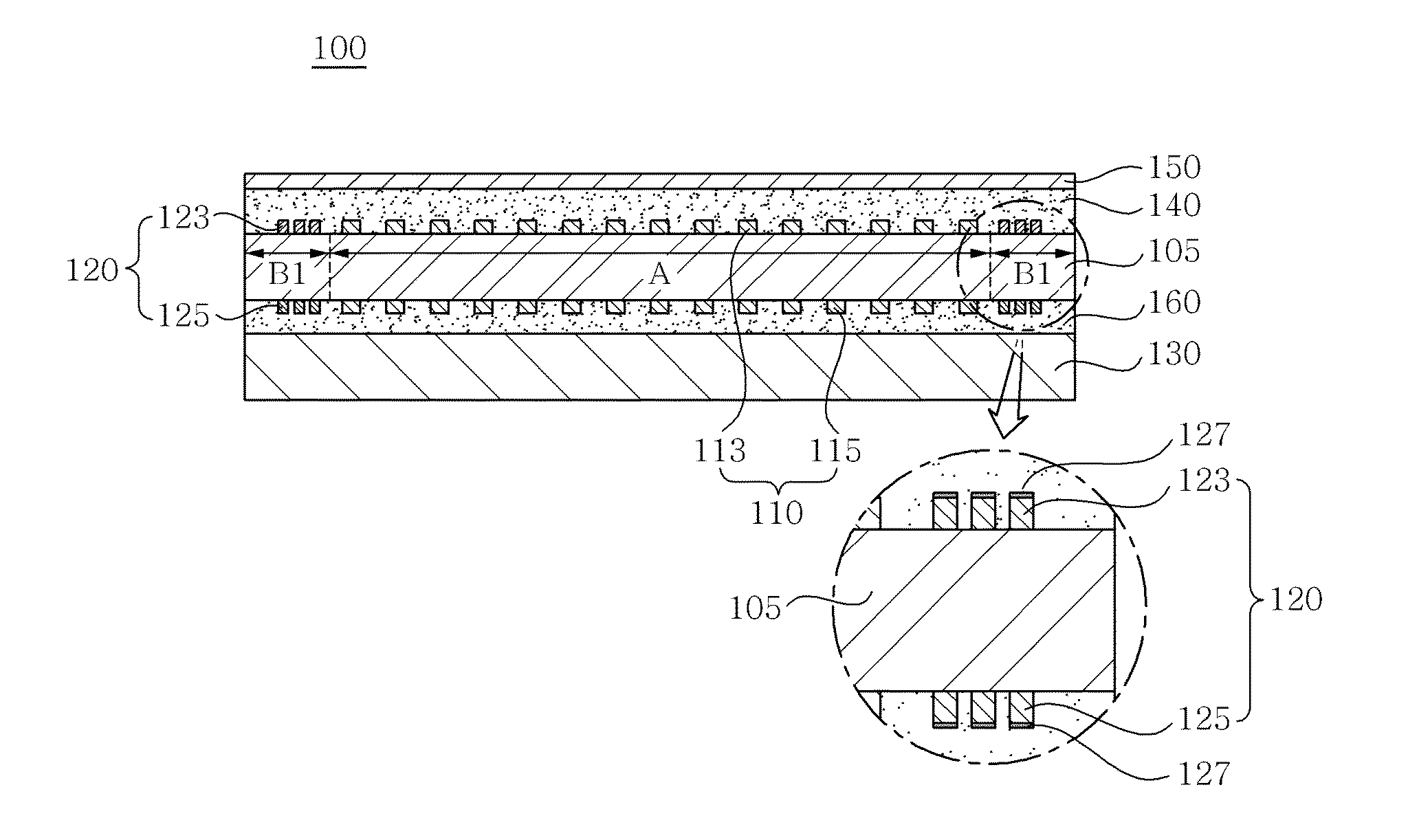
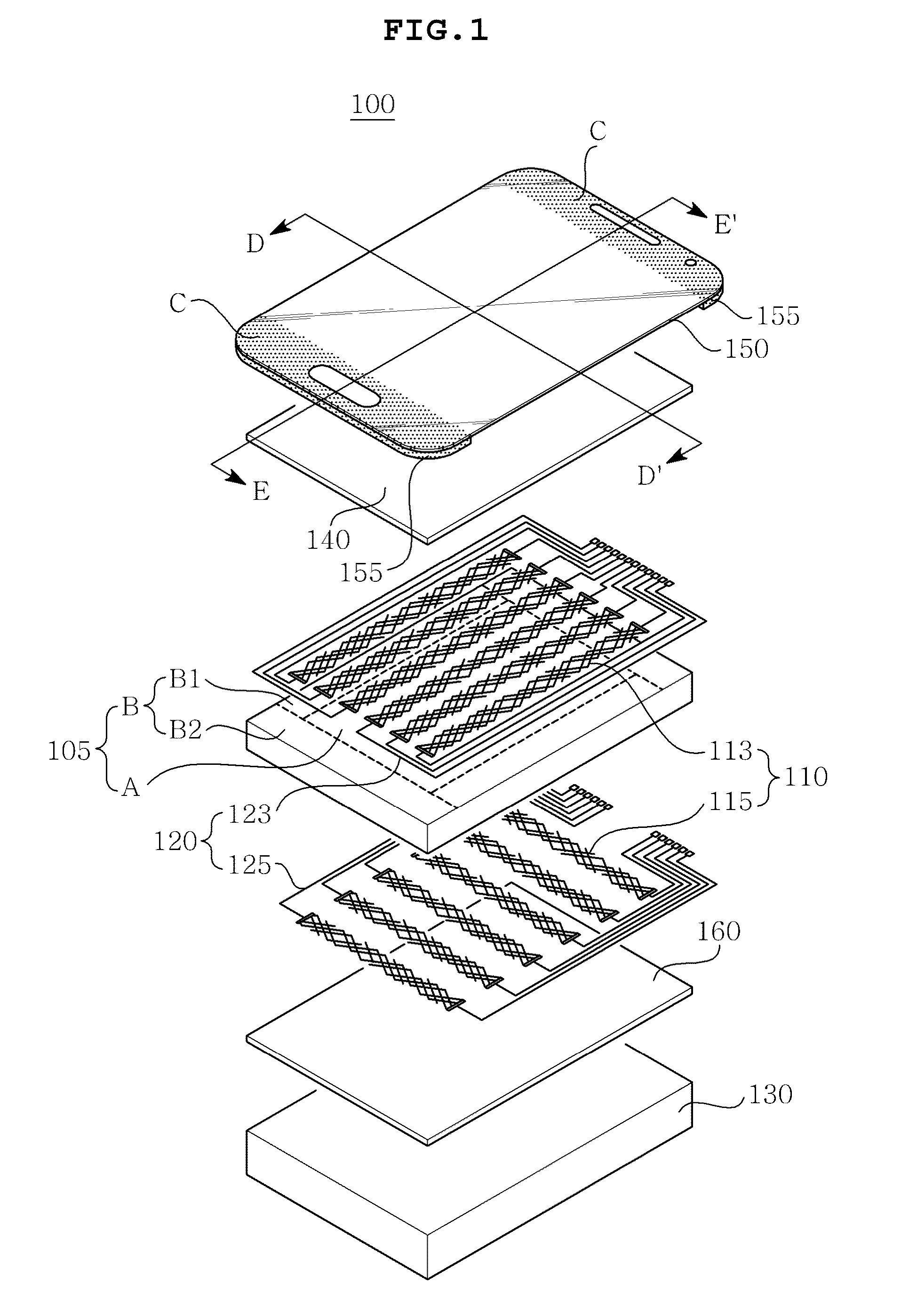
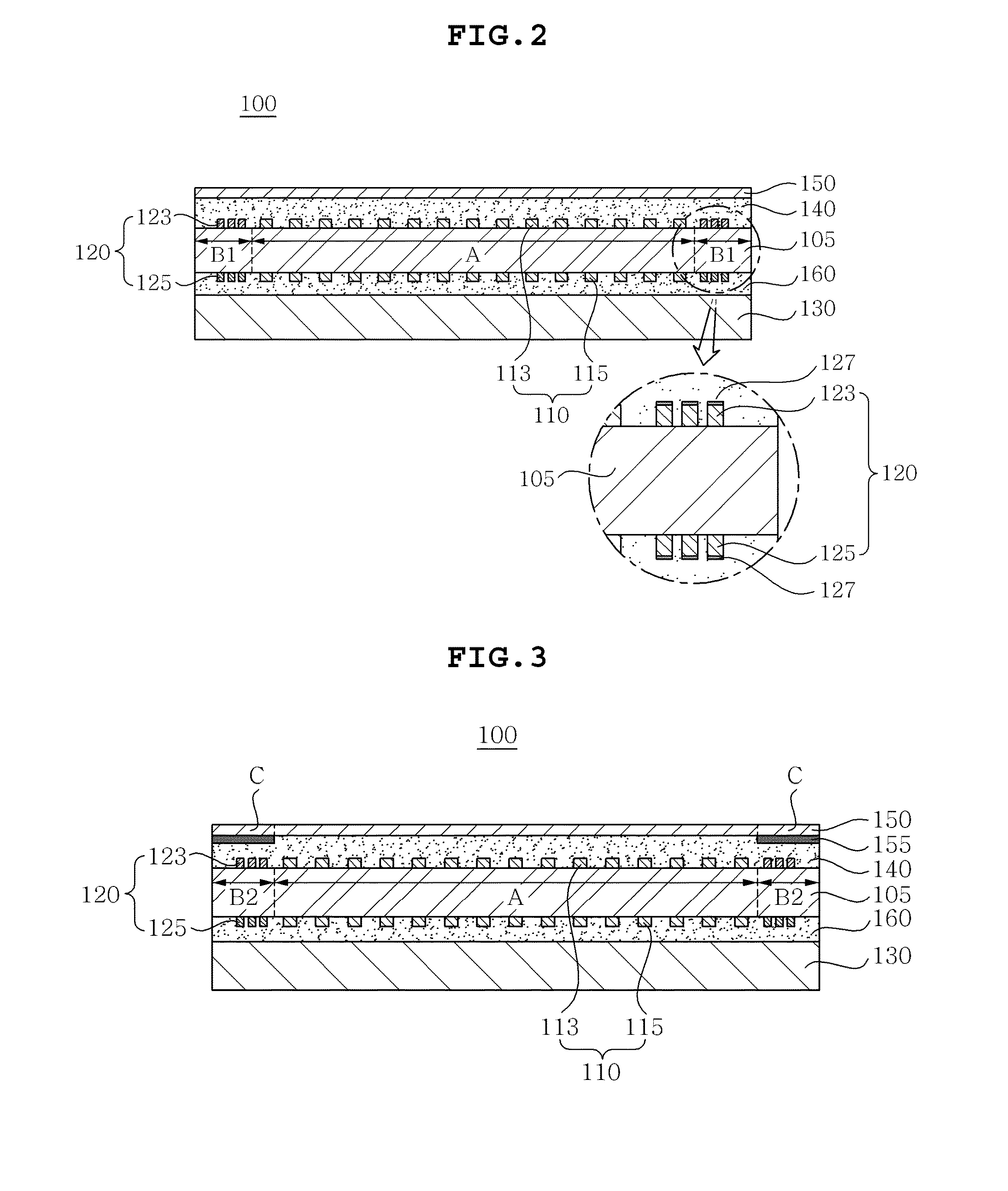
Disclosed herein is a touch panel. The touch panel 100 according to a preferred embodiment of the present invention is configured to include a transparent substrate 105 that is partitioned into an active region A and a bezel region B disposed at an edge of the active region A, an electrode pattern 110 formed in the active region A, an electrode wiring 120 formed in the bezel region B so as to be connected with the electrode pattern 110, and a display 130 outputting specific light to the bezel region B.

Description

CROSS REFERENCE TO RELATED APPLICATION[0001]This application claims the benefit of Korean Patent Application No. 10-2012-0104039, filed on Sep. 19, 2012, entitled “Touch Panel”, which is hereby incorporated by reference in its entirety into this application.BACKGROUND OF THE INVENTION[0002]1. Technical Field[0003]The present invention relates to a touch panel.[0004]2. Description of the Related Art[0005]In accordance with the growth of computers using a digital technology, devices assisting computers have also been developed, and personal computers, portable transmitters and other personal information processors execute processing of text and graphics using a variety of input devices such as a keyboard and a mouse.[0006]While the rapid advancement of an information-oriented society has widened the use of computers more and more, it is difficult to efficiently operate products using only a keyboard and a mouse currently serving as an input device. Therefore, the necessity for a devic...

Claims


Application Information

Patent Timeline
Patent Type & Authority Applications(United States)
IPC IPC(8): G06F3/041
CPCG06F3/041G06F2203/04103G06F2203/04112G06F3/0446G06F3/0445G06F3/04164G02F1/13338G06F3/044
Inventor LEE, WAN JAELEE, SEUNG MINKIM, YOUN SOOPARK, HO JOON
Owner SAMSUNG ELECTRO MECHANICS CO LTD
Learn More