
Travel division line recognition apparatus and travel division line recognition program

a technology for traveling division lines and recognition programs, which is applied in the field of apparatus and programs for recognizing travel division lines, can solve the problems of insufficient inability to calculate the depth of vehicles, and inability to accurately calculate vehicle depth, so as to achieve stably performed elimination of vehicle edges, suppress erroneous recognition of travel division lines, and eliminate vehicle edges

Active Publication Date: 2017-05-30
DENSO CORP
View PDF46 Cites 5 Cited by
  • Summary
  • Abstract
  • Description
  • Claims
  • Application Information

AI Technical Summary

Benefits of technology

This approach stabilizes the elimination of vehicle edges and suppresses erroneous recognition, thereby maintaining a high recognition rate of travel division lines.

Problems solved by technology

When a vehicle is recognized from a monocular image, it may not be possible to calculate the depth of the vehicle.
Moreover, even when a vehicle is recognized from stereo images, the accuracy of depth calculation of the vehicle may be low.
When the edges of a vehicle are eliminated without taking into consideration the depth of the vehicle, the elimination of vehicle edges may be insufficient.
In addition, when the edges of a vehicle are eliminated using inaccurate depth, the elimination of vehicle edges may be excessive or insufficient.
There is a risk that elimination of vehicle edges may not be stably performed.
As a result, erroneous recognition of cruising the travel division line may occur, leading to a decrease in the recognition rate of the travel division line.
The calculating unit includes a solid object processing unit that sets a suppression area based on the recognition of solid objects including vehicles, and reduces the degree of reliability of the division line candidate present within the suppression area.

Method used


Image

  • Travel division line recognition apparatus and travel division line recognition program
  • Travel division line recognition apparatus and travel division line recognition program
  • Travel division line recognition apparatus and travel division line recognition program

Examples


Embodiment Construction

[0022]An embodiment of a travel division line recognition apparatus will hereinafter be described with reference to the drawings. The travel division line recognized by the travel division line recognition apparatus according to the present embodiment are used in lane keeping assist (LKA) control and lane deviation warning.

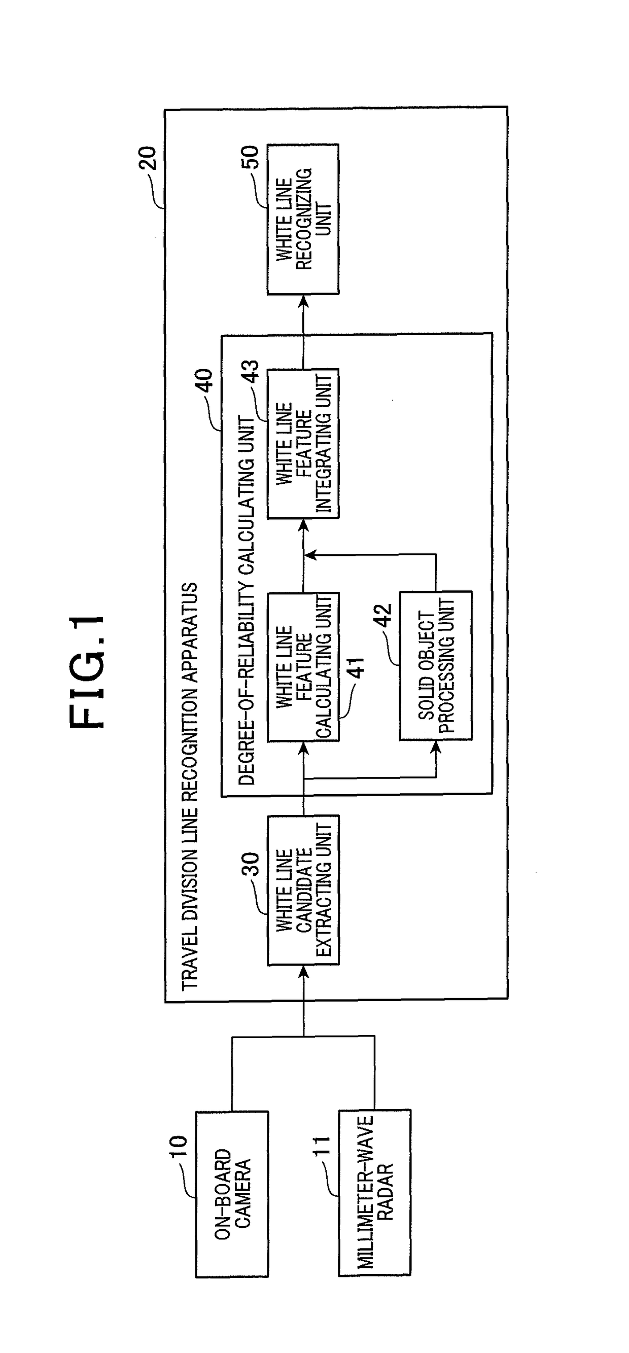
[0023]First, a configuration of the travel division line recognition apparatus according to the present embodiment will be described with reference to FIG. 1. A travel division line recognition apparatus 20 according to the present embodiment is an on-board apparatus that recognizes white lines (division lines) on a road using images from an on-board camera 10 and the detection results from a millimeter-wave radar 11.

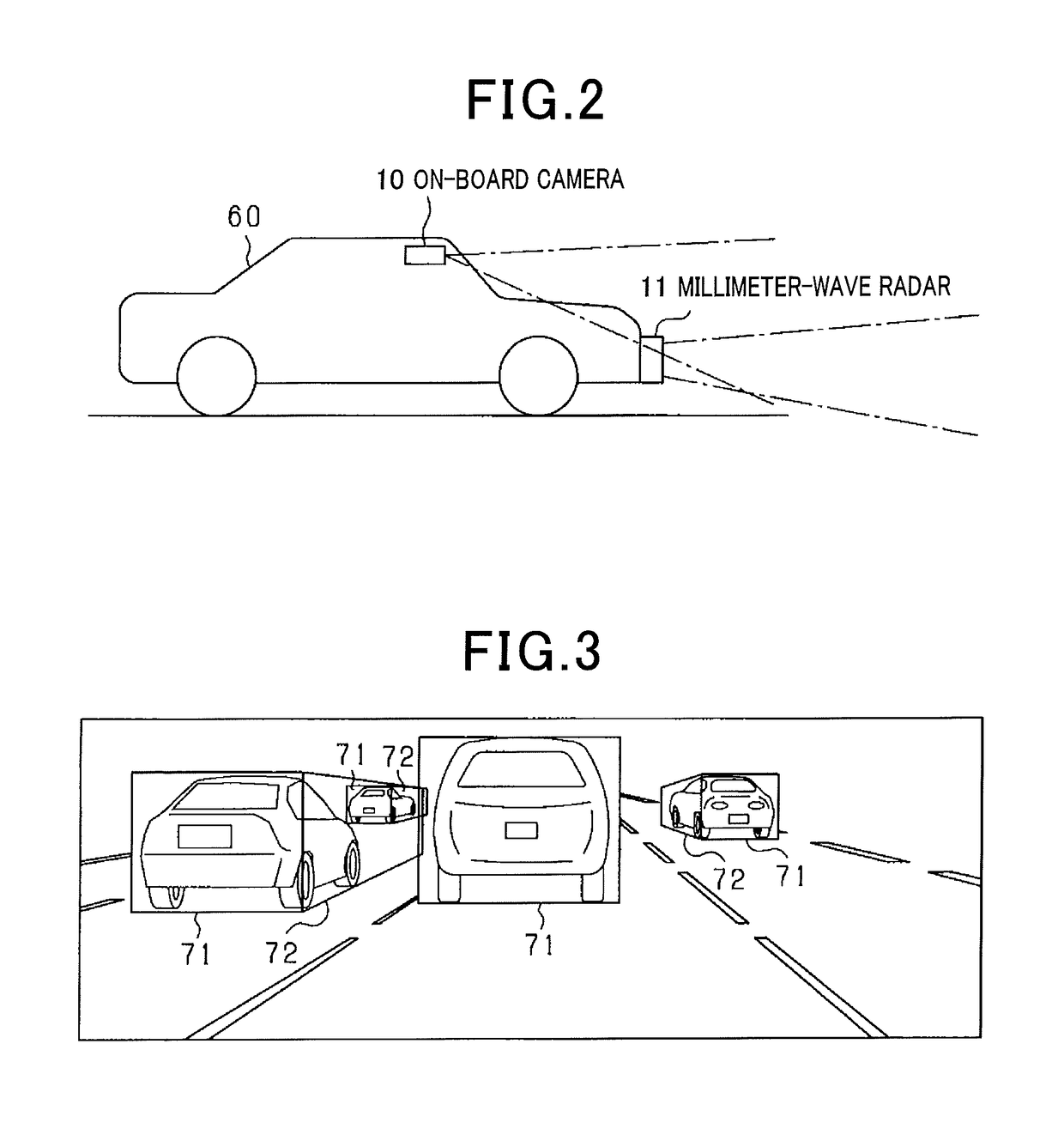
[0024]The on-board camera 10 is configured by at least one of a charge-coupled device (CCD) camera, a complementary metal-oxide-semiconductor (CMOS) image sensor, and a near-infrared camera. As shown in FIG. 2, the on-board camera 10 is mounted on an ...


PUM


Abstract

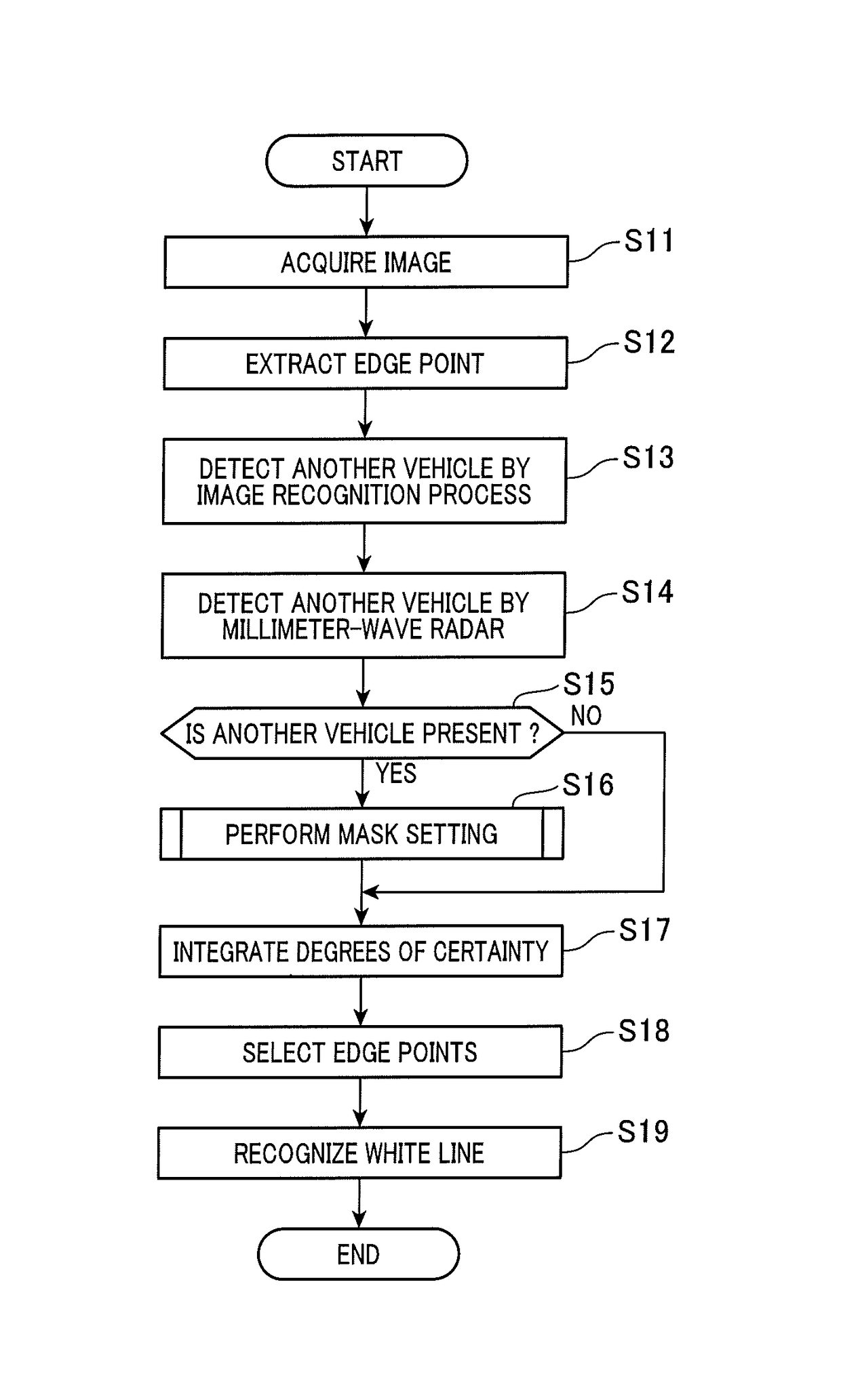
In a travel division line recognition apparatus, an extracting unit extracts a travel division line candidate from an image of a surrounding environment including a road, captured by an on-board camera. A calculating unit calculates a degree of reliability that the extracted travel division line candidate will be the travel division line. A recognizing unit selects the travel division line candidate based on the calculated degree of reliability, and recognizes the travel division line using the selected travel division line candidate. In the calculating unit, a solid object processing unit recognizes solid objects including vehicles, sets a suppression area including a frontal-face suppression area covering a frontal face of the other vehicle and a side-face suppression area covering a side face of the other vehicle, based on the recognized solid objects, and reduces the degree of reliability of the travel division line candidate present within the suppression area.

Description

CROSS-REFERENCE TO RELATED APPLICATION[0001]This application is based on and claims the benefit of priority from Japanese Patent Application No. 2014-060280, filed Mar. 24, 2014, the disclosure of which is incorporated herein in its entirety by reference.BACKGROUND[0002]Technical Field[0003]The present invention relates to an apparatus and a program for recognizing a travel division line on a road on a road from images captured by an on-board camera.[0004]Related Art[0005]Apparatuses have been proposed that recognize a travel division line on a road from images captured by an on-board camera, and use the recognized travel division line for driving assistance. Among such apparatuses, there is an apparatus that eliminates the edges of solid objects, such as vehicles, from the images to accurately recognize the travel division line.[0006]For example, in JP-A-2006-331389, stereo images that have been captured by a pair of on-board cameras are used. Solid objects are surrounded by frames...

Claims


Application Information

Patent Timeline
Patent Type & Authority Patents(United States)
IPC IPC(8): G06K9/00G06K9/62
CPCG06K9/00798G06K9/00805G06K9/6293G06V20/588G06V20/58G06V10/811G06F18/256
Inventor KUMANO, SYUNYAKAWASAKI, NAOKISUZUKI, SHUNSUKETAKAFUJI, TETSUYA
Owner DENSO CORP
Learn More