Toilet Flush Valve Assemblies

a technology for flushing valves and toilets, applied in water installations, flushing devices, constructions, etc., can solve problems such as no longer requiring a minimum “hold down time”, problems may be encountered, and the effect of affecting the valve body and the two-inch inl

Active Publication Date: 2014-04-03
AS AMERICA
View PDF5 Cites 28 Cited by
  • Summary
  • Abstract
  • Description
  • Claims
  • Application Information

AI Technical Summary

Benefits of technology

[0024]A diameter of the lower outlet end of the valve body is preferably about 2 inches, and the float preferably has a buoyant force which is equivalent to a force needed to displace at least about 70 grams to about 170 grams of water with air, more preferably at least about 100 grams to about 140 grams of water with air, and most preferably at least about 120 grams of water with air. The float is also capable of maintaining the valve in an open position in a tank having a starting water head of about 9 inches to about 10 inches above the valve body so as to provide a peak flow rate measured at the outlet of the flush valve of at least about 5900 ml / s.

Problems solved by technology

Although these prior solutions noted in the above-patents effectively remove waste from toilet bowls within government guidelines, such guidelines no longer mandate a minimum “hold down time”.
Problems may be encountered when using an elevated valve body having an optimal radiused inlet designed to enhance flow and maximize hydraulic energy through the valve body with a standard flapper-type valve cover.
A traditional flush valve cover's performance used with such a valve body and a two-inch inlet becomes affected in terms of its ability to close when appropriate, sometimes closing prematurely, and in terms of its ability to re-open.
This problem can be exacerbated in a radiused inlet valve body design, because the extension of the inlet opening due to the presence of the radius, which is optimized for high-efficiency flow through the valve body, can require an even larger sized flapper to cover the opening created by the radius which increases the force required to open the valve and actuate the flush.
Furthermore, the high velocity flow enabled by the radiused inlet can counteract the buoyant force of the flapper and cause the valve to close prematurely.
These factors combine to make it difficult to properly open and close a standard flapper on a valve assembly configured for use in an HPT or, preferably an HET and having an elevated valve body and radiused inlet, even in comparison to standard low profile, non-elevated flush valve bodies having standard flapper-type valve covers, for example, a commercially available Fluidmaster® Flush Valve Model 507.
Another problem encountered in prior art flush valve designs is that such flush valves, whether suitable for high-efficiency toilets or not, when optimized for flow design, have outlets which, when installed, introduce fluid flow directly into an inlet chamber of a toilet bowl having a lower floor which lies in a plane perpendicular to the flow coming out of the flush valve outlet.
The impact of the contact against the bottom surface of the inlet chamber (which may be a manifold) of water under a high flow rate through the valve caused by flushing, introduces undesirable turbulence which reduces the hydraulic energy available from the water exiting the outlet of the flush valve.
Although the bulb provides required buoyancy, it occupies space in the flow path when the valve is opened, which can reduce the flow rate below its maximum potential.
When greater buoyancy is required, the size of the bulb must increase, further exasperating this drawback.

Method used


Image

  • Toilet Flush Valve Assemblies
  • Toilet Flush Valve Assemblies
  • Toilet Flush Valve Assemblies

Examples


example

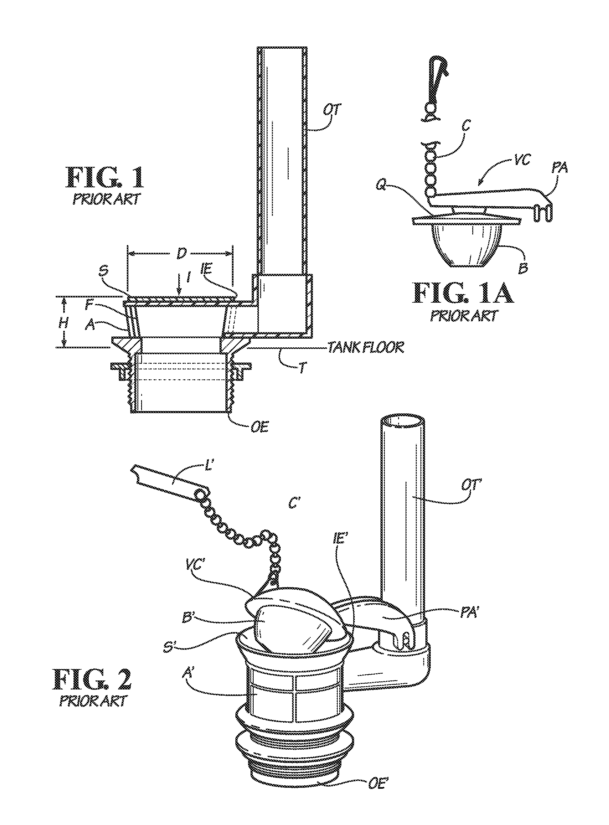
[0095]The average of the flow rate properties of a standard commercially available flush valve assembly (Fluidmaster®507 flush valve) according to the prior art as shown in FIGS. 1, 1A and 2 were compared to an average of the flow rate properties of a flush valve assembly made according to an embodiment herein after two consecutive flush cycles using varying water levels. The results of the comparison between the peak flow rates at certain tank water head levels are shown in Table 1, and represented graphically in FIG. 11. This data demonstrates that the peak flow rate of the flush valve assembly of the present invention was higher than that of the flush valve assembly of the prior art over a variety of tank water levels.

TABLE 1COMPARATIVEINVENTIVEWATER LEVEL -EXAMPLE - PEAKEXAMPLE - PEAKINCHESFLOW RATE (ml / s)FLOW RATE (ml / s)6 288448747 320052648 355057729 3848596210 4 294664011 4 524689012 5 0167332


PUM


Abstract

Flush valve assemblies are described herein which include a valve body; a flush valve cover detachably connected to a flush line; a pivot mechanism capable of opening and closing the flush valve cover upon actuation; wherein the flush line is connected at a first end to a flush actuating device and at a second end to the flush valve cover, the line being capable of raising and lowering the cover upon actuation; and a float situated above the cover and connected to the flush line at a point between the first and the second ends of the flush line or by a separate float line connected to the cover. The float is sufficiently buoyant and capable of resisting the force of flowing water and keeping the flush valve cover open to allow flush water to pass through the valve body before closing the cover when the valve body is installed on a toilet.

Description

CROSS-REFERENCE TO RELATED APPLICATIONS[0001]This application claims the benefit under 35 U.S.C. §119(e) of U.S. Provisional Patent Application No. 61 / 708,892, filed Oct. 2, 2012, entitled, “Toilet Flush Valve Assemblies,” the entire disclosure of which is incorporated herein by reference.BACKGROUND OF THE INVENTION[0002]1. Field of the Invention[0003]The present invention relates to plumbing in a water closet or toilet water tank of a toilet, and more particularly to flush valve assemblies for use in the water tank of a toilet assembly.[0004]2. Description of Related Art[0005]Toilets and toilet assemblies for removing waste products are well known. Typically, toilets incorporate three systems that work together to perform the flushing action. Those systems are (1) the bowl, which includes a waste receptacle in fluid communication with a drain line (2) the flush mechanism, and (3) the refill mechanism. Working in concert, these three systems enable the flushing function of the toile...

Claims


Application Information

Patent Timeline
Patent Type & Authority Applications(United States)
IPC IPC(8): E03D5/094
CPCE03D5/094E03D1/308E03D1/33
Inventor JENSEN, ROBERT M.
Owner AS AMERICA
Why Eureka
Try Eureka