Variable and serrated scanning in laser projectors

a laser projector and variable scanning technology, applied in the field of miniature projectors, can solve the problems of limiting the utility of the projector to environments with low ambient background light, increasing the power of the laser, and consuming the power of the battery quickly,

Inactive Publication Date: 2014-04-10
MAGNOLIA LICENSING LLC
View PDF2 Cites 8 Cited by
  • Summary
  • Abstract
  • Description
  • Claims
  • Application Information

AI Technical Summary

Benefits of technology

[0010]A method is provided that comprise: receiving image data for an image to scan; generating light beams responsive to the image data; forming a horizontal scan profile to direct the light beams in which the horizontal scan profile comprises cycles having oscillating amplitudes that are substantially parallel to a first axis (X-axis) and substantially perpendicular to a second axis (Y-axis); forming a cyclic wobulation responsive to the cycles; forming a vertical scan profile that includes the cyclic wobulation; and scanning the light beams according to a wave pattern that is a composite of the vertical scan profile and the horizontal scan profile to form the image such that the light beams are driven vertically parallel to the second axis (Y-axis) from a first edge to an ending edge while oscillating horizontally parallel the first axis (X-axis). The method can further include generating a baseline vertical scan profile of motion along the second axis as a function of time; providing or selecting a cyclic wobulation profile of motion along the second axis versus time in which the cyclic wobulation profile comprises individual wobulation cycles in which one wobulation cycle corresponds to one half of a single wave of a wave pattern and another wobulation cycle corresponds to a second half of the single wave; and adding the cyclic wobulation profile to the baseline vertical scan profile to obtain the vertical scan profile. The baseline vertical scan

Problems solved by technology

Unfortunately, miniature laser projectors generally exhibit low light output, thereby limiting their utility to environments with low ambient background light.
Maximum brightness for these devices can be increased by increasing the power of the output; however

Method used


Image

  • Variable and serrated scanning in laser projectors
  • Variable and serrated scanning in laser projectors
  • Variable and serrated scanning in laser projectors

Examples


Embodiment Construction

)

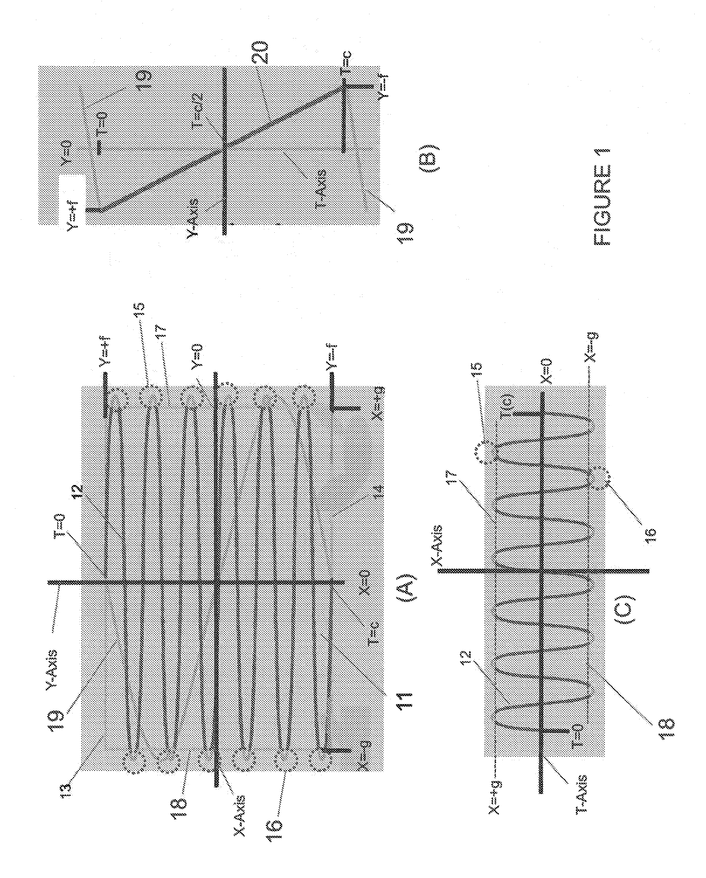
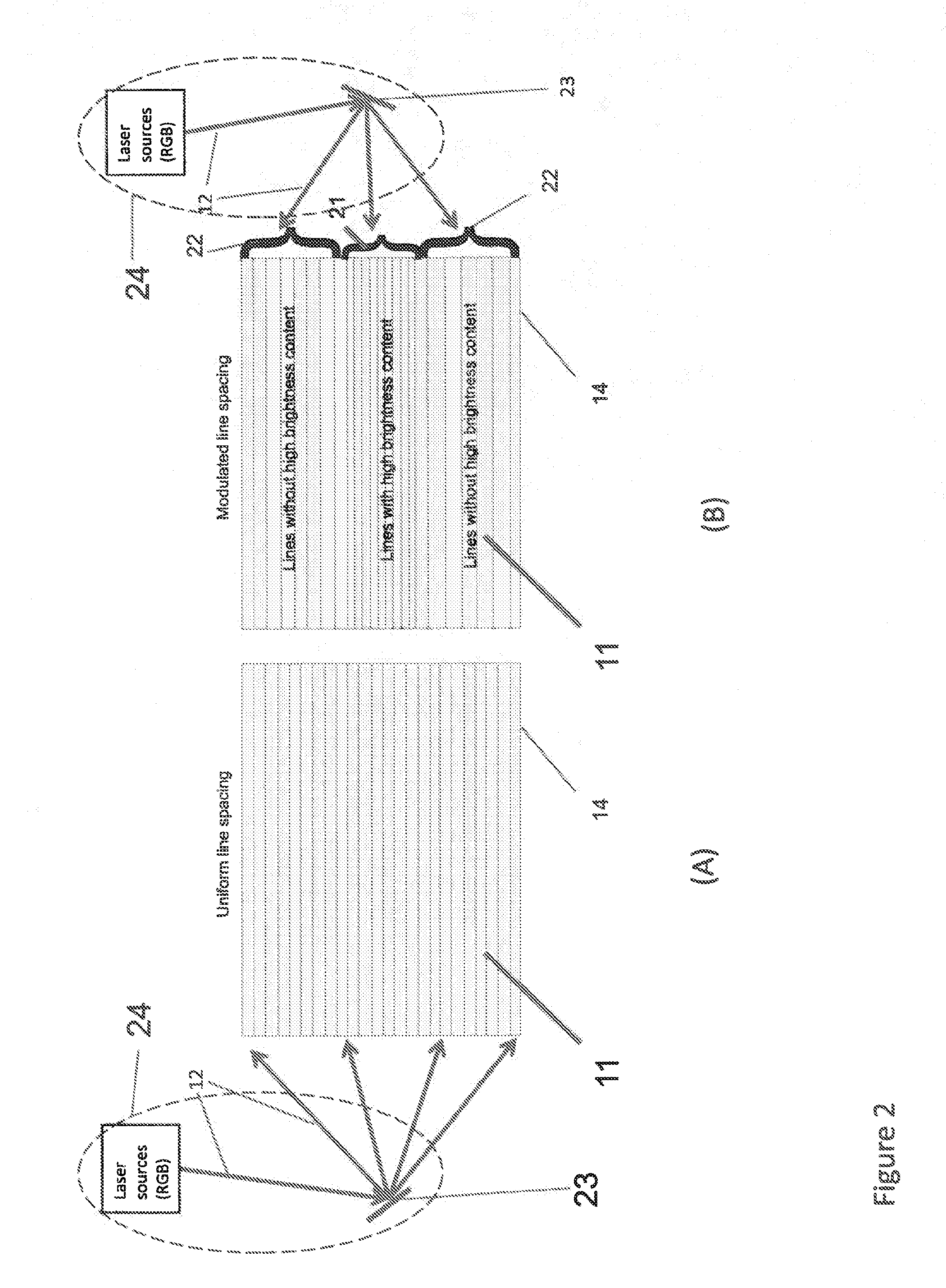
[0022]To increase the peak brightness and maintain and / or improve image uniformity of miniature displays, which can be laser based or light emitting diode based, embodiments of the invention are disclosed that incorporate certain modulations of the scan velocity and / or serrated scanning patterns. The serrated scanning, which will be described in greater detail below, can generally be achieved by having some wobulation feature in the vertical and / or horizontal scan profiles, wherein wobulation implies some subtle oscillation in a dimension about a locus of points. Subtle oscillations implies that the wobulation motion is substantial smaller than or a fraction of the complete range of scan motion in the dimension.

[0023]An important consideration in the miniature display incorporated in the invention is that unlike in CRTs, which require a blanked horizontal retrace interval to produce a uniform horizontal scan pattern, a blanking horizontal retrace is not practical. The reason is a h...


PUM


Abstract

A miniature projector is provided that comprises: a means for providing at least three different light beams of different color; and a means for scanning the light beams; wherein the scanning means is adapted to scan the light beams according to a pattern from a first edge to an ending edge in the screen to form an image, the pattern being a wave pattern of scan lines such that amplitudes oscillates along a first axis as the beams progressively scan along a second axis, the second axis being perpendicular to the first axis, and wherein the wave pattern is a composite of a vertical scan profile and horizontal scan profile and the vertical scan profile has a cyclic wobulation corresponding to the amplitudes.

Description

CROSS-REFERENCE TO RELATED APPLICATIONS[0001]This application claims priority from U.S. Provisional Application 61 / 520,067 filed Jun. 3, 2011 which is incorporated by reference herein in its entirety and this application relates to U.S. Provisional Application 61 / 520,068 filed on Jun. 3, 2011.FIELD OF THE INVENTION[0002]The invention relates to miniature projectors and methods for operating miniature projectors.BACKGROUND[0003]Miniature laser projectors, which have been referred to as pico projectors, nano projectors, and micro projectors, are generally battery operated portable projectors that have been gaining popularity because their small size makes them convenient for certain applications. The devices can be connected to handheld devices or laptops and can display images on screens or walls.[0004]Unfortunately, miniature laser projectors generally exhibit low light output, thereby limiting their utility to environments with low ambient background light. These laser-based units ...

Claims


Application Information

Patent Timeline
IPC IPC(8): H04N9/31
CPCH04N9/3135G09G3/002G09G2320/0626G09G2360/16G09G3/025H04N5/2628H04N5/74G03B21/00G09G3/02
Inventor RUMREICH, MARK FRANCIS
Owner MAGNOLIA LICENSING LLC
Why Eureka
Try Eureka