
Cryogenic tank

a cryogenic tank and tank body technology, applied in the field of cryogenic tanks, can solve the problems of aircraft damage, one or more persons on board the aircraft being injured, and the pressure load on the tank being too high,

Active Publication Date: 2014-05-01
GENERAL ELECTRIC CO
View PDF5 Cites 24 Cited by
  • Summary
  • Abstract
  • Description
  • Claims
  • Application Information

AI Technical Summary

Benefits of technology

The patent text describes a cryogenic tank with a unique shape that can withstand loads and distribute them along three directions. The tank has a shell with internal reinforcement frames that help it withstand high acceleration and prevent rupturing. This design makes the tank more robust and safe for use in aircraft and other applications where cryogenic fluids are needed.

Problems solved by technology

For example, cryogenic fluids may be stored at elevated pressure relative to the surroundings, resulting in a pressure load on the tank.
Many known cryogenic tanks cannot withstand the inertia loads experienced during operation of the aircraft without rupturing and / or becoming dislodged within the aircraft.
Cryogenic fluid may leak and / or spill out of a ruptured cryogenic tank, which may cause damage to the aircraft and / or injury to one or more persons on-board the aircraft.
Moreover, a cryogenic tank that has become dislodged may cause impact damage to the aircraft and / or impact injury to one or more persons on-board the aircraft.
But, such cryogenic tanks are too heavy and / or are not volumetrically efficient.

Method used


Image

  • Cryogenic tank
  • Cryogenic tank
  • Cryogenic tank

Examples


Embodiment Construction

[0014]The following detailed description of certain embodiments will be better understood when read in conjunction with the appended drawings. It should be understood that the various embodiments are not limited to the arrangements and instrumentality shown in the drawings.

[0015]As used herein, an element or step recited in the singular and proceeded with the word “a” or “an” should be understood as not excluding plural of said elements or steps, unless such exclusion is explicitly stated. Furthermore, references to “one embodiment” are not intended to be interpreted as excluding the existence of additional embodiments that also incorporate the recited features. Moreover, unless explicitly stated to the contrary, embodiments “comprising” or “having” an element or a plurality of elements having a particular property may include additional such elements not having that property.

[0016]Various embodiments of cryogenic tanks are provided for containing a cryogenic fluid (e.g., liquid nat...


PUM

PropertyMeasurementUnit
Accelerationaaaaaaaaaa
Efficiencyaaaaaaaaaa

Abstract

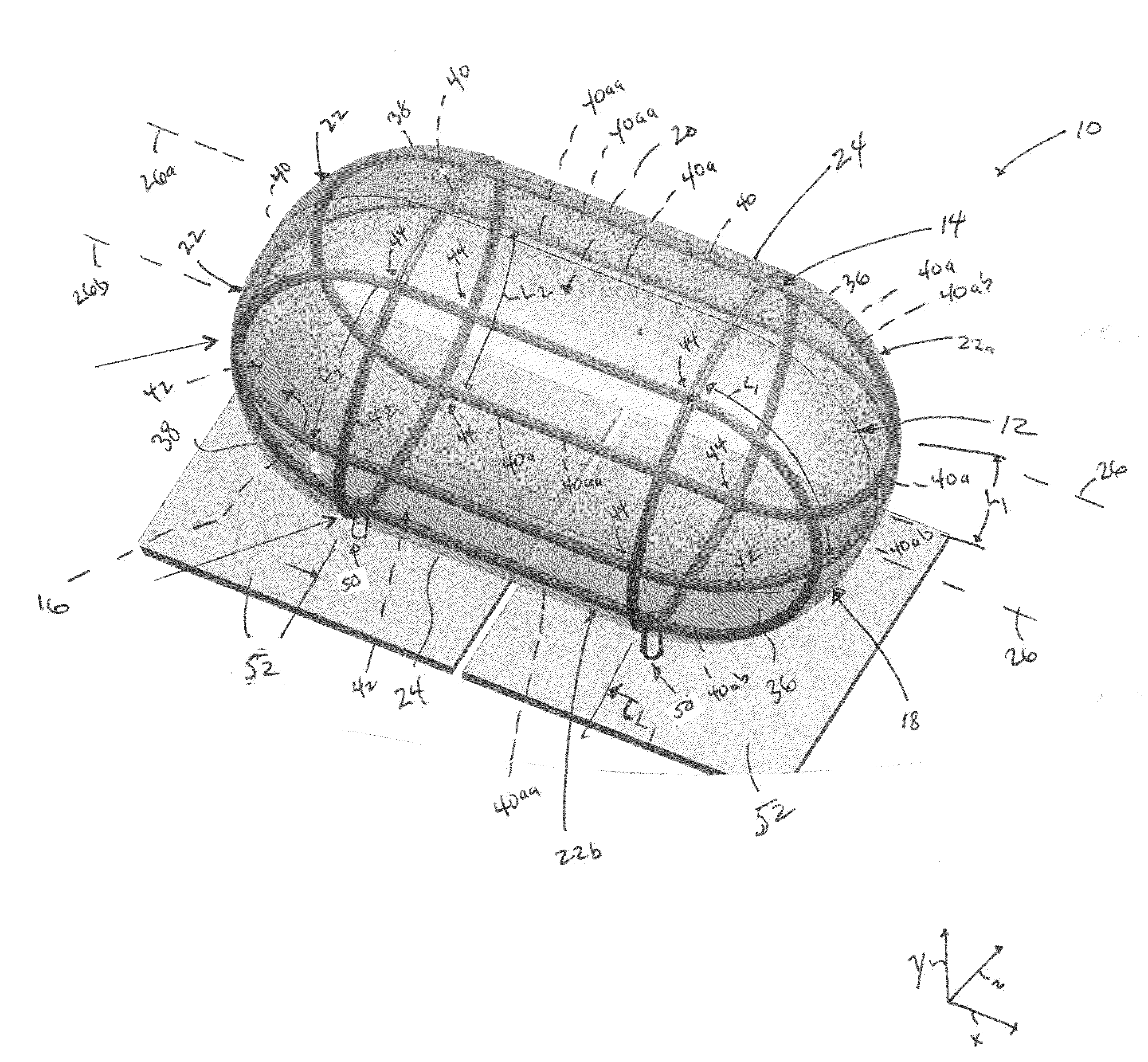
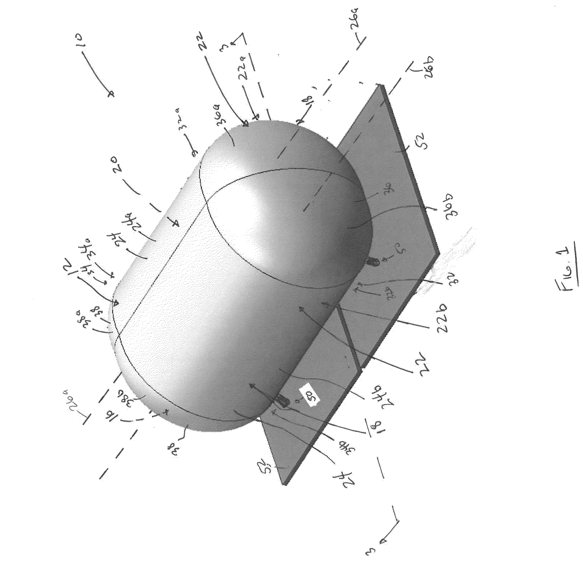
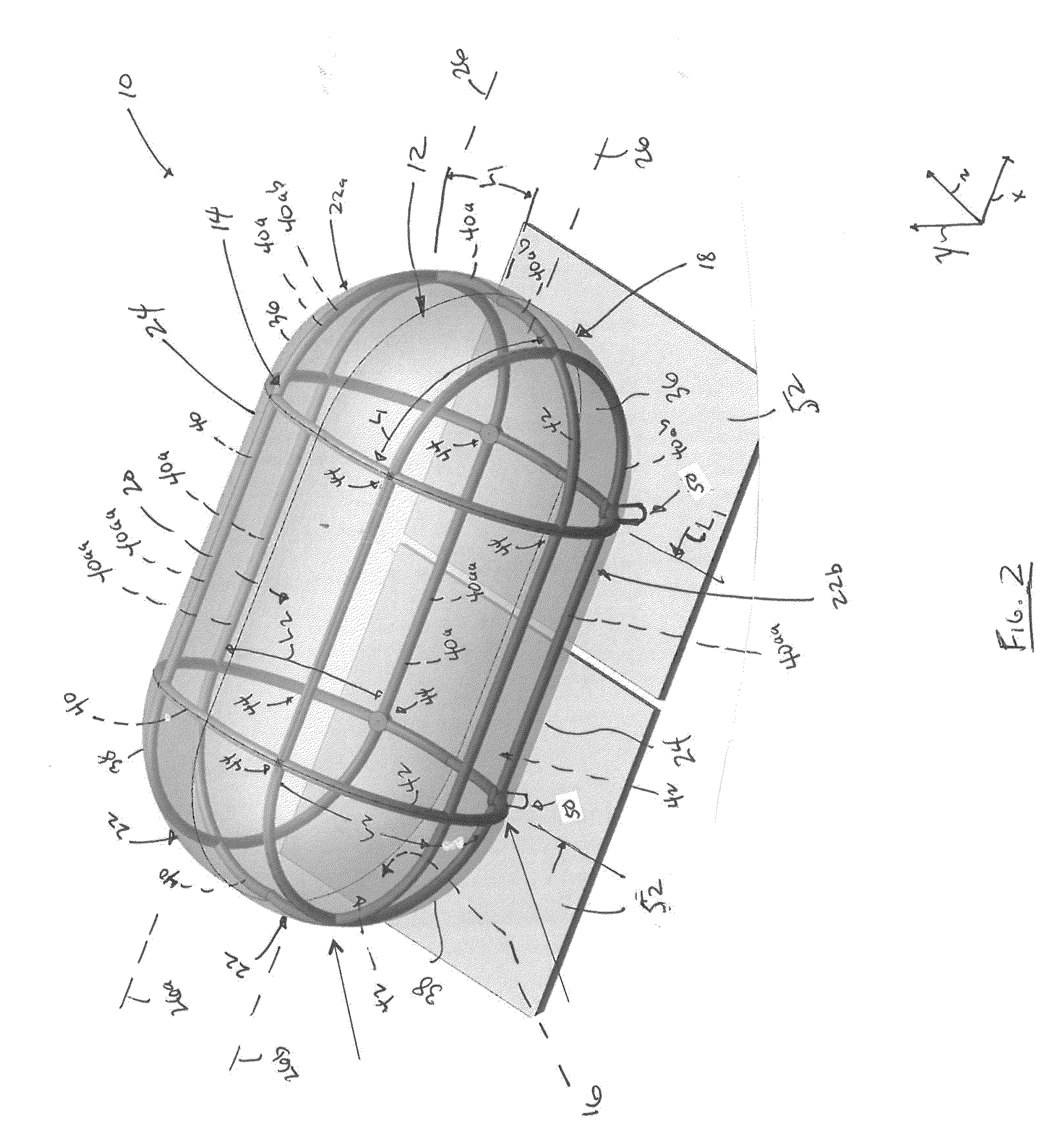
A cryogenic tank includes a shell having an interior side, an exterior side, and an internal volume that is bounded by the interior side. The shell has a shape that includes at least two elongated lobes that are defined by partial cylinders that intersect each other. The partial cylinders extend lengths along central longitudinal axes that are offset from each other. The lobes include opposite domes that extend at opposite ends of the length of the corresponding partial cylinder. The cryogenic tank includes an internal reinforcement frame having a web of elongate frame members extending within the internal volume. The frame members extend along the interior side of the shell such that lengths of the frame members extend along paths that follow the profile of the interior side of the shell. The internal reinforcement frame is configured to distribute loads exerted on the shell along at least three different directions.

Description

BACKGROUND[0001]Cryogenic fluids are sometimes used on-board aircraft. For example, some aircraft engines are configured to use natural gas as fuel. The natural gas is stored on-board the aircraft as liquid natural gas (LNG), which is a cryogenic fluid. Cryogenic fluids are stored on-board aircraft within a cryogenic tank that holds a volume of the cryogenic fluid. Various loads may be exerted on the cryogenic tank during operation of the aircraft. For example, cryogenic fluids may be stored at elevated pressure relative to the surroundings, resulting in a pressure load on the tank. Various additional loads may be exerted on a cryogenic tank during flight operations of the aircraft as the aircraft maneuvers (e.g., turns, dives, climbs, accelerates, and / or the like) through an airspace. Moreover, various loads may be exerted on a cryogenic tank during emergency takeoffs and during emergency landings of the aircraft, for example due to the relatively large accelerations and / or deceler...

Claims


Application Information

Patent Timeline
IPC IPC(8): B64D37/06B64D37/08B64D47/00F17C5/02F17C13/08
CPCB64D37/06B64D37/30F17C1/14F17C2201/0152F17C2201/054F17C2203/013F17C2203/0325F17C2203/0329F17C2203/035F17C2203/0383F17C2203/0391F17C2203/0629F17C2203/0636F17C2203/0646F17C2203/0648F17C2205/018F17C2221/033F17C2223/0161F17C2223/033F17C2223/035F17C2260/011F17C2270/0189
Inventor SIMPSON, JAMES EDWARD
Owner GENERAL ELECTRIC CO
Learn More