
T-shaped gastrostomy tube retention device

a retention device and gastrostomy technology, applied in the field of medical devices, can solve the problems of large size of the balloon, affecting the function of the body, and not being able to securely retain the tube inside the body cavity,

Inactive Publication Date: 2014-05-08
COOK MEDICAL TECH LLC
View PDF4 Cites 1 Cited by
  • Summary
  • Abstract
  • Description
  • Claims
  • Application Information

AI Technical Summary

Benefits of technology

The patent describes devices and methods for keeping tubes in body cavities. These devices have elongated segments that rotate around a hinge to engage the inside of the body cavity. The elongate segments can be parallel or perpendicular to the tube depending on the need. The devices can be connected to the end of a tube or located inside the tube. The technical effect of the invention is the ability to securely hold tubes in body cavities, minimizing trauma and allowing for easier placement and retention.

Problems solved by technology

However, none of the existing retention devices securely retain the tube within the body cavity, require little or no maintenance, and also minimize the size of the surgical opening required to deliver the tube and retention device.
Furthermore, the relatively large size of the balloon can block internal body passageways or otherwise interfere with bodily functions.
Deformable collars include complex and expensive elements that deform based on force applied from the exterior of the body.
Permanently attached flanges include deformable retaining elements that allow the device to collapse when force is applied, however, the deformability also reduces the resistance to removing the device.

Method used


Image

  • T-shaped gastrostomy tube retention device
  • T-shaped gastrostomy tube retention device
  • T-shaped gastrostomy tube retention device

Examples


Embodiment Construction

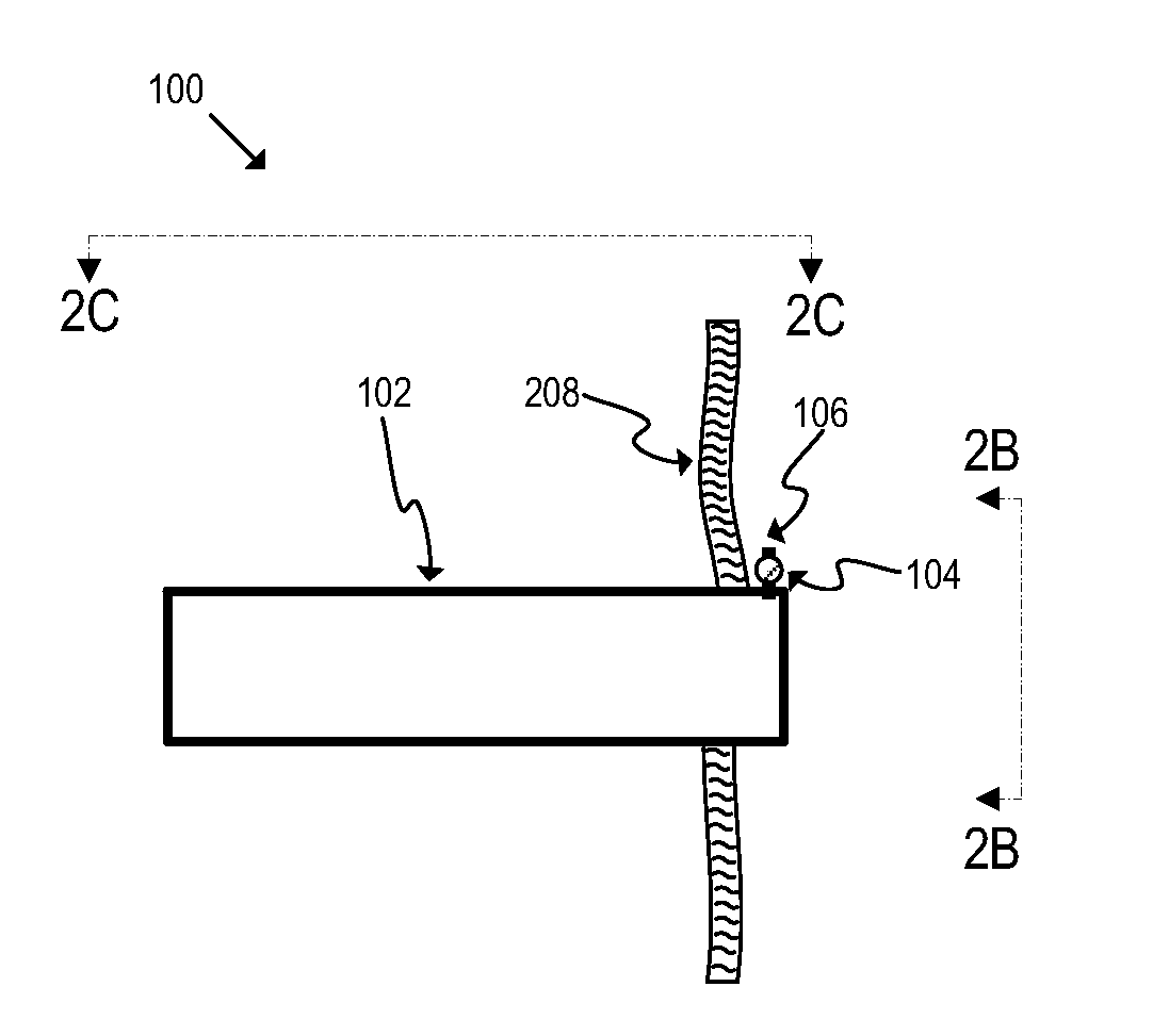
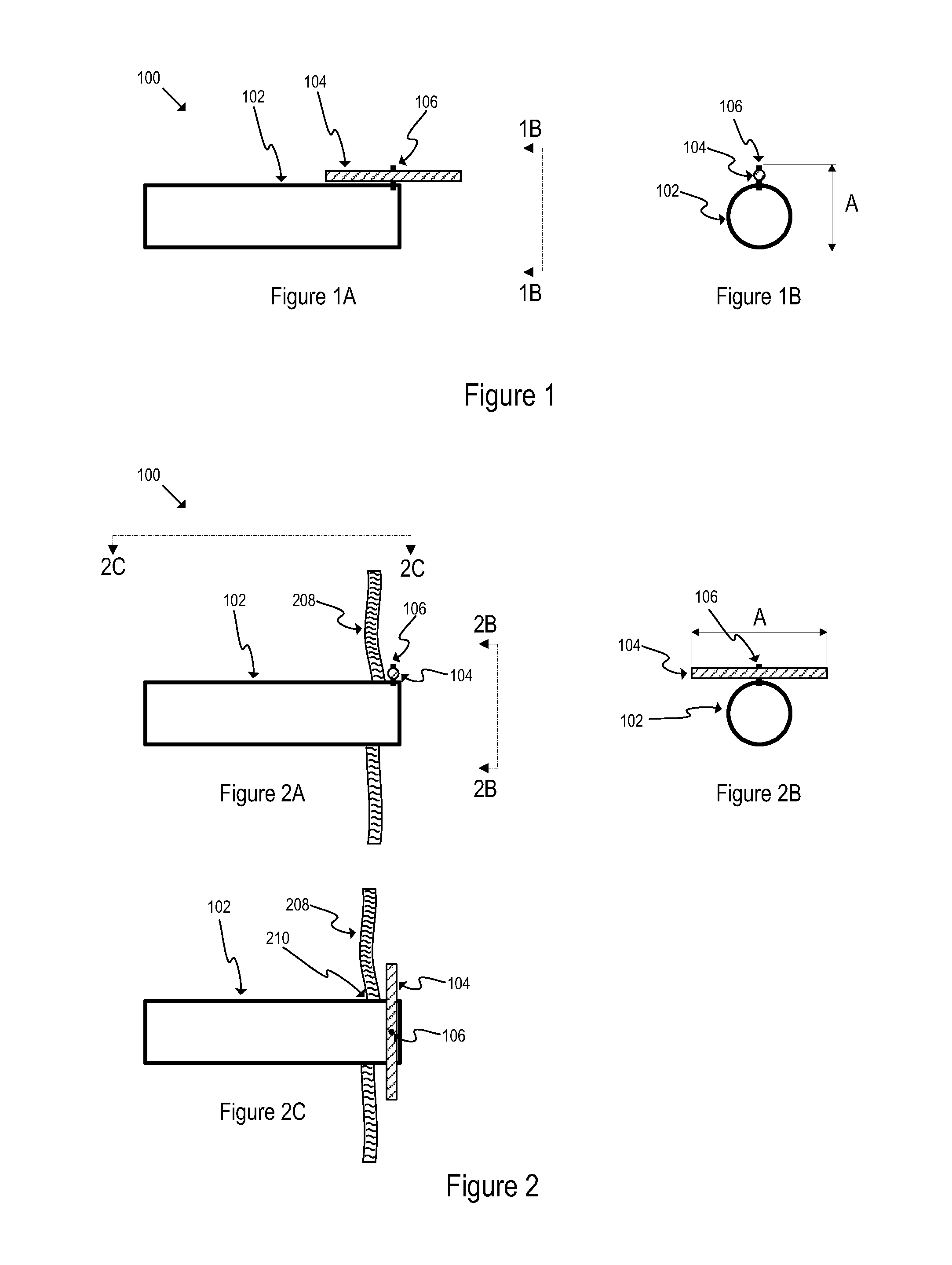
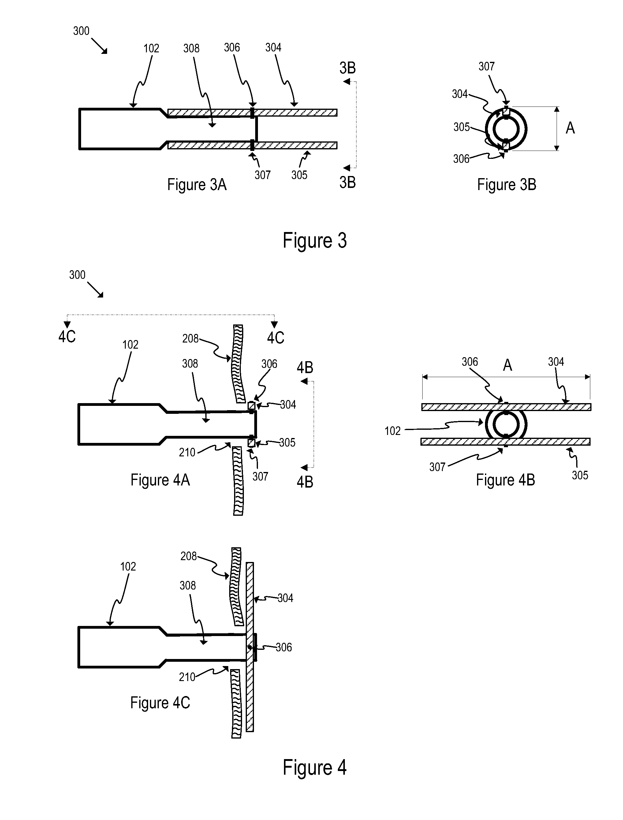
[0028]Various embodiments of the tube retention device 100 according to the present invention are shown in FIGS. 1-7. In general, the tube retention device 100 may comprise an elongate segment 104 attached to the distal end of a tube 102 through a rotatable hinge 106. Rotatable hinge 106 may allow elongate segment 104 to spin or rotate around the connection point such that the position of elongate segment 104 in reference to tube 102 may be modified. Elongate segment 104 may have at least one dimension that is larger than the diameter of tube 102. As will be explained in greater detail below, during insertion into the body cavity, elongate segment 104 may be positioned substantially parallel to tube 102. Parallel position of elongate segment 104 may allow the diameter of the surgical opening from the exterior of the body to the interior of the body to be minimized. The opening may be substantially the same size as the diameter of the tube to be inserted into the opening. After inser...


PUM


Abstract

A tube retention device may prohibit the removal of a tube from a body cavity. The tube retention device may include an elongate segment connected to the tube through a rotatable hinge. The elongate segment may have a length larger than the diameter of the tube. The elongate segment may rotate about the rotatable hinge from an insertion position, in which the length of the elongate segment is parallel to the tube, to a retention position, in which the length of the elongate segment is perpendicular to the tube. In the retention position, engagement of the elongate segment with the interior surface of the body cavity may prohibit removal of the tube from the body cavity.

Description

BACKGROUND OF THE INVENTION[0001]1. Field of the Invention[0002]The invention relates to medical devices, more particularly to the retention of tubes inside a body cavity.[0003]2. Description of the Related Art[0004]Tubes are inserted into bodies for multiple reasons, such as feeding tubes or drainage tubes. Feeding tubes may be required to provide nutrition if normal ingestion of food becomes difficult or impossible for a patient. Certain patients, such as comatose patients, stroke victims, or those with a compromised gastrointestinal tract, may require a tube that is introduced to the stomach or intestinal tract through a surgical opening in the body, such as a stoma. Once inserted into the body cavity, an internal retention device is required to ensure the tube stays in the desired location and is not inadvertently removed by the patient.[0005]Various types of retention devices exist, including balloons, deformable collars, and permanently attached flanges. However, none of the e...

Claims


Application Information

Patent Timeline
IPC IPC(8): A61M39/00
CPCA61M39/0247A61M2039/0255A61M2039/0261A61M2039/0291A61J15/0015A61J15/003
Inventor DELANEY, KEVIN
Owner COOK MEDICAL TECH LLC
Learn More