
Dental arch model and method of making the same

a dental arch and model technology, applied in the field of dental arch models and methods, can solve the problems of undesirable shift, variation in solidification depth and layer thickness, and certain drawbacks of known additive processes

Active Publication Date: 2014-06-19
GLOBAL FILTRATION SYST
View PDF6 Cites 46 Cited by
  • Summary
  • Abstract
  • Description
  • Claims
  • Application Information

AI Technical Summary

Benefits of technology

The patent text describes a dental arch model and methods of making them using three-dimensional rapid prototyping and manufacturing techniques. However, current methods have drawbacks such as variations in solidification depth and layer thickness in the build axis direction during the model manufacturing process. The use of removable supports can also cause damage to the arch model and distort the alignment of the upper and lower arches when connecting them. The patent aims to address these issues by providing dental arch models and methods with improved connectors that can better maintain the model's shape and stability during and after manufacturing.

Problems solved by technology

However, known additive processes have certain drawbacks.
It has been discovered that certain connector geometries may cause variations in solidification depth and layer thickness in the build axis direction during arch manufacturing as well as an undesirable shift in the plane perpendicular to the build axis relative to the object data used to create the arch.
However, the use of supports necessarily wastes solidifiable material and lengthens the time to build the arch model.
In addition, when building upper arches, the removal of supports may damage or otherwise disrupt the smoothness of the upper arch's bottom surface.
This in turn may make it difficult to align and register the upper arch with the lower arch when connecting the two via an articulator.
The use of removable supports can damage or distort the pin holes making the arch unsuitable for pin registration.
The elimination of supports can also be problematic because without supports the model is solidified in direct contact with a build platform which can also cause damage to the arch model upon removal.
In addition, trapped volumes of liquid are created within the three-dimensional model during the build process which can result in unwanted sections of cured material and distortions to the model relative to the object data that defines it.

Method used


Image

  • Dental arch model and method of making the same
  • Dental arch model and method of making the same
  • Dental arch model and method of making the same

Examples


example

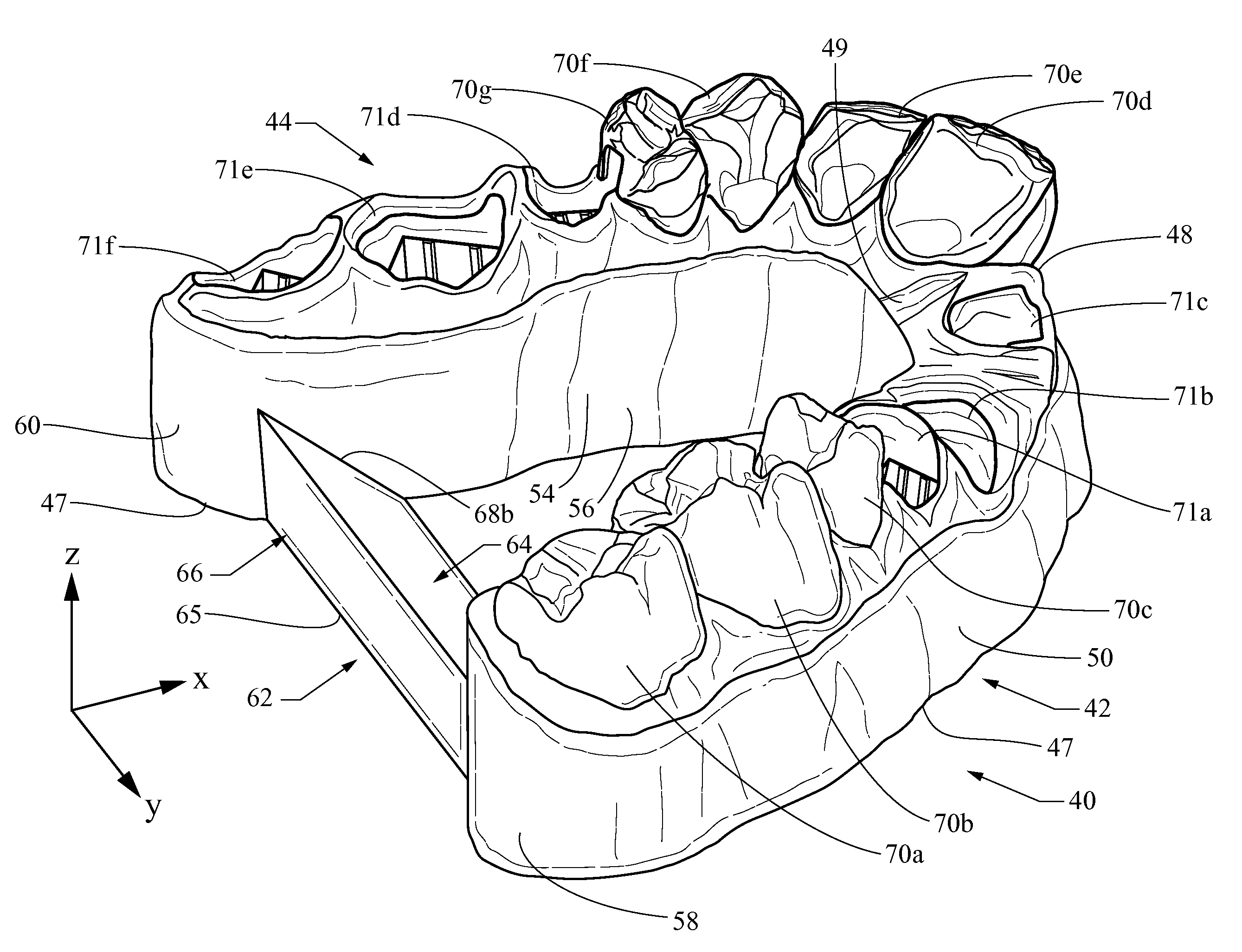
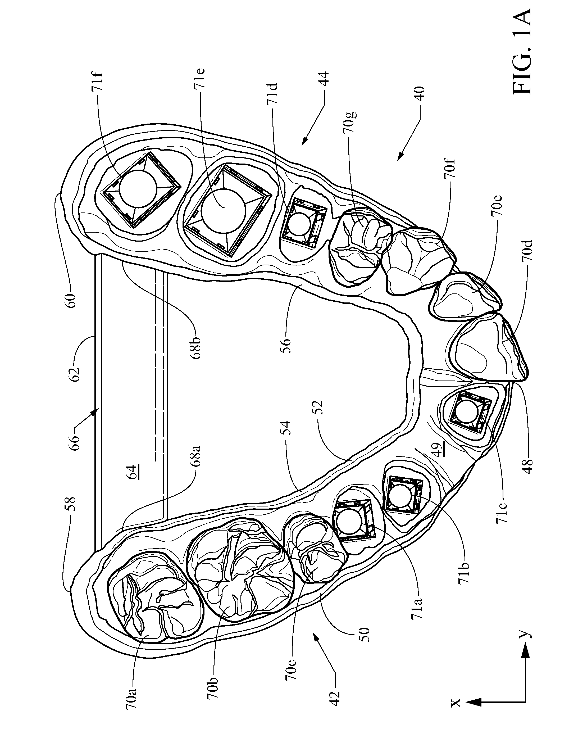
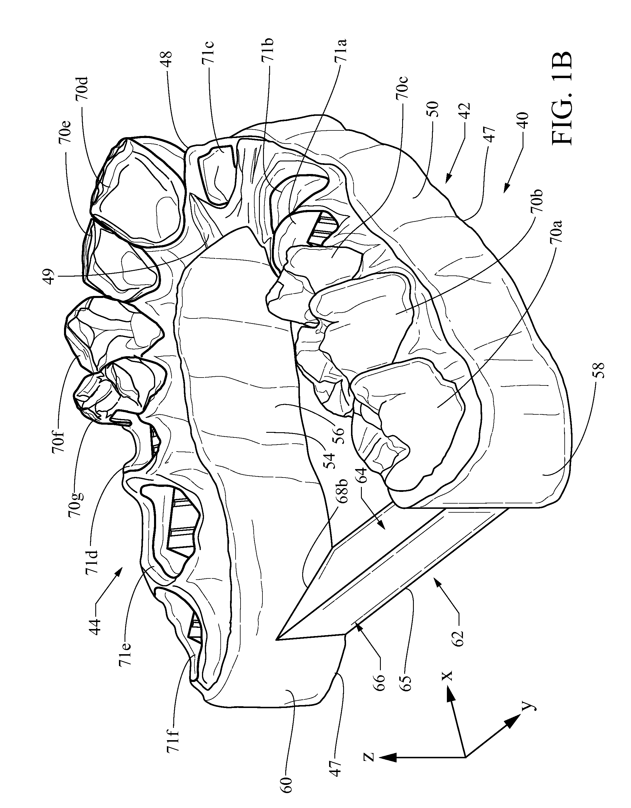
[0066]The dental arch model 40 depicted in FIG. 7 is built using an ULTRA three-dimensional printer supplied by Envisiontec, Inc. of Dearborn, Mich. The arch model is constructed using an HTM 140 IV acrylic resin solidifiable material supplied by Envisiontec, Inc. A color compound (Orange Dye 10) is added to the HTM 140 IV resin in an amount of 0.25 g / kg HTM 140 IV. Voxel data representative of the dental arch model 40 is supplied with a maximum voxel thickness of 50 microns. Following post-curing, the dental arch model is measured and compared to the corresponding object data using a magnification of 150×. There is no appreciable deviation in the x-y plane even above the upper-most voxel layer of connector 142. In addition, the measured voxel layer thickness does not deviate appreciably from the 50 micron specification even above the upper-most voxel layer of connector 142.


PUM

PropertyMeasurementUnit
anglesaaaaaaaaaa
angleaaaaaaaaaa
viscosityaaaaaaaaaa

Abstract

A dental arch model and method for making the same is shown and described. The dental arch model includes a connector having opposite ends that connect to a respective one of the arch legs. The connector has a three-dimensional shape but does not include a surface that is both planar and parallel to the base of the arch connector along more than two thirds of the arch connector's length. In certain examples, the connector is in the shape of a prism or a trapezoid. In other examples, the connector has an upper surface that is sloped relative to the base of the arch connector. The arch connector may also include a plurality of fluid passageways for allowing fluid flow from an interior area between the inner walls of the arch connector to a location outside of the connector.

Description

CROSS REFERENCE TO RELATED APPLICATIONS[0001]This application claims the benefit of U.S. Provisional Patent Application No. 61 / 738,120, filed Dec. 17, 2012, the entirety of which is hereby incorporated by reference.FIELD[0002]The disclosure relates to dentistry, and more particularly, to dental arch models and methods of making the same.DESCRIPTION OF THE RELATED ART[0003]Conventional dentistry techniques involve the fabrication of models of the upper and / or lower arches of the teeth for a variety of reasons such as simulating the relative positioning of upper and lower teeth and fabricating crowns or orthodontic appliances. Such known fabrication methods involve, for example, having the patient bite into a pliable material (e.g., alginate or silicone impression material) while it is in a pliable state then hardening the material to yield a semi-flexible impression of the patient's dental arch. Dental gypsum is then poured into the impression and removed from it to create the arch m...

Claims


Application Information

Patent Timeline
Patent Type & Authority Applications(United States)
IPC IPC(8): A61C13/34
CPCA61C13/34A61C13/0004B29C64/112B29C64/124B29C64/135B29C64/129B29C64/153B29C33/3842A61C13/0013A61C13/0006A61C13/0019B29C33/3835A61C13/0018
Inventor EL-SIBLANI, ALI
Owner GLOBAL FILTRATION SYST
Learn More