Dispensing assembly in vending machine

Inactive Publication Date: 2014-06-26
HON HAI PRECISION IND CO LTD
View PDF17 Cites 8 Cited by
  • Summary
  • Abstract
  • Description
  • Claims
  • Application Information

AI Technical Summary

Benefits of technology

The patent describes a dispensing device with a bracket, tray, and shaft for dispensing products. Currently, the shaft is secured to the bracket using complicated and costly securing methods. The technical effect of the patent is to simplify and reduce the cost of securing the shaft to the bracket.

Problems solved by technology

However, the securing process of the shaft is time-consuming, and a securing structure of the shaft can be complicated and costly.

Method used


Image

  • Dispensing assembly in vending machine
  • Dispensing assembly in vending machine
  • Dispensing assembly in vending machine

Examples


Embodiment Construction

[0013]The disclosure is illustrated by way of example and not by way of limitation in the figures of the accompanying drawings in which like references indicate similar elements. It should be noted that references to “an” or “one” embodiment in this disclosure are not necessarily to the same embodiment, and such references mean “at least one.”

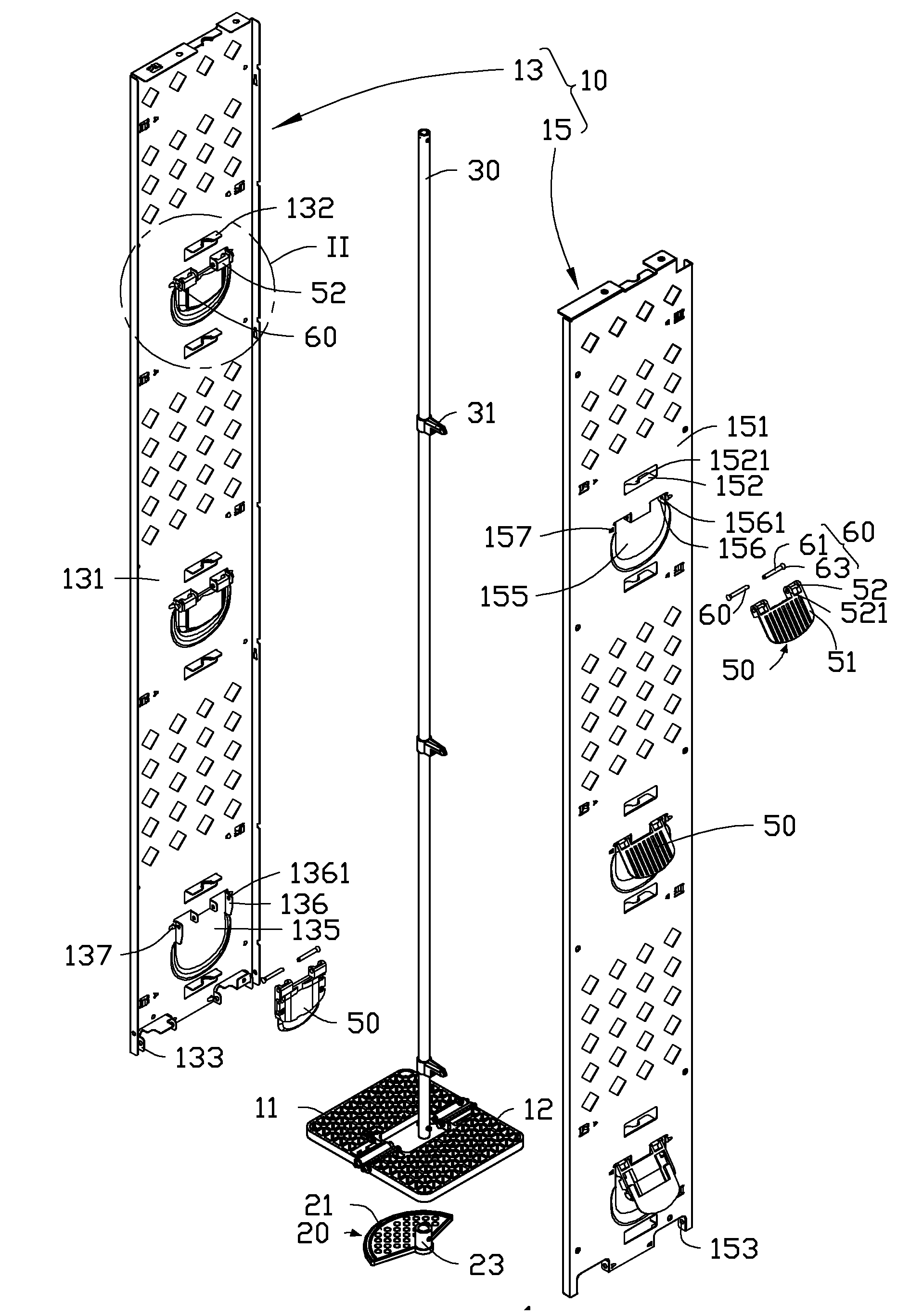
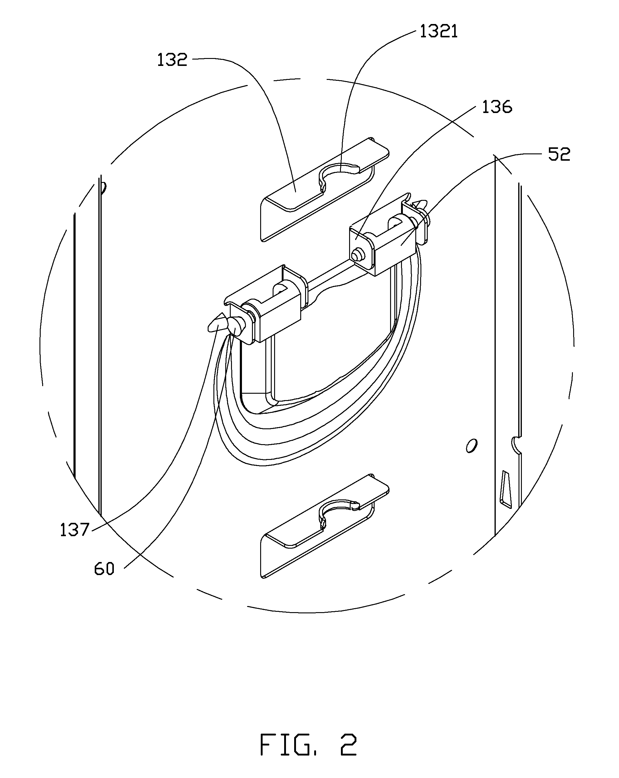
[0014]FIG. 1 shows one embodiment of a dispensing device. The dispensing device includes a bracket 10, a first base 11, a second base 12, a tray 20, a shaft 30, and a plurality of blocking plates 50.

[0015]The bracket 10 includes a first frame 13 and a second frame 15.

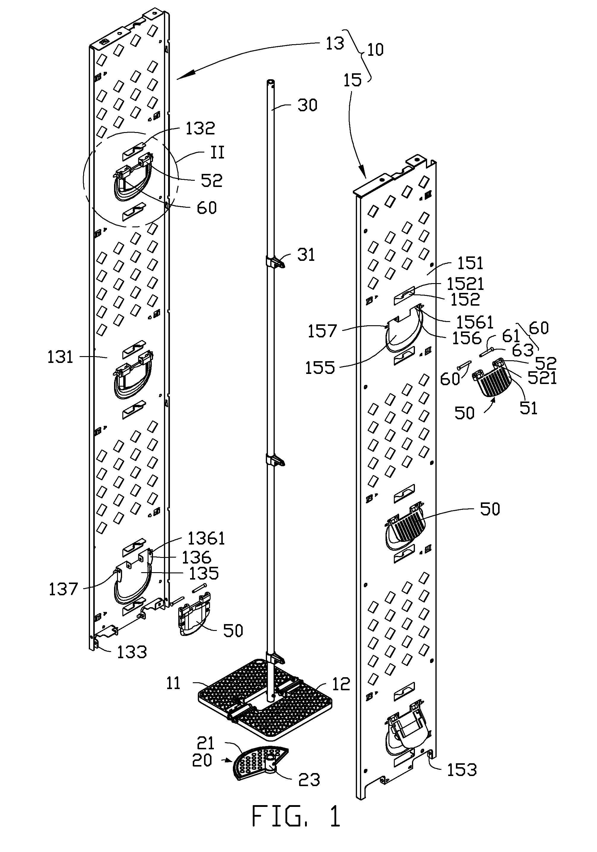
[0016]FIG. 1 and FIG. 2 show the first frame 13 including a first mounting plate 131 and a plurality of first limiting pieces 132, extending from a side of the first mounting plate 131. Each first limiting piece 132 defines a first cutout 1321. Two pairs of first pivoting pieces 133 are located at a bottom end of the first mounting plate 131. Each first pivoting piece 133 is substa...


PUM


Abstract

A dispensing device includes a bracket, a base, a tray, a blocking plate, and a jacking member. The tray holds the base to keep a plurality of products on the base. The tray is rotatable to release the base, allowing one item of the products to drop down from the base. The bracket includes a first mounting plate, a first limiting piece extending from the first mounting plate, a second mounting plate, and a second limiting piece extending from the second mounting plate. The first limiting piece defines a first cutout, the second limiting piece defines a second cutout, and the first cutout and the second cutout cooperatively form a receiving hole rotatably receiving the receiving hole therein.

Description

BACKGROUND[0001]1. Technical Field[0002]The present disclosure relates to vending machines, and particularly to a dispensing assembly in the vending machines.[0003]2. Description of Related Art[0004]In many direct type dispensing devices, a dispensing assembly for dispensing products includes a bracket, a tray, and a shaft. The bracket includes a base for placing the products thereon. The tray is located under the base. The tray is secured to the shaft. The shaft is rotatable under an action of a motor to rotate the tray to hold the base or release the base. When the tray supports the base, the products are blocked by the base and cannot drop down for the customer to pick up. When the tray releases the base, the base is free, causing one item of products to drop down to the customer bin by gravity. Generally, the shaft is inserted in a plurality of shaft sleeves, and then the shaft sleeves are secured to the bracket by screws or latches. However, the securing process of the shaft is...

Claims


Application Information

Patent Timeline
IPC IPC(8): G07F11/50
CPCG07F11/50G07F11/48
Inventor CHEN, YUN-LUNG
Owner HON HAI PRECISION IND CO LTD
Why Eureka
Try Eureka