
Mounting device for mounting motor installation plate in vending machine

a technology for installing devices and motors, which is applied in the field of mounting devices for installing plates for motors in vending machines, can solve the problems of time-consuming installation plate secure process, high cost, and complicated flange structur

Inactive Publication Date: 2014-07-24
HON HAI PRECISION IND CO LTD
View PDF18 Cites 0 Cited by
  • Summary
  • Abstract
  • Description
  • Claims
  • Application Information

AI Technical Summary

Benefits of technology

The patent text discusses the common design of vending machines and how the dispensing assembly works. However, the text notes that the process of securing the motor to the tray is time-consuming and complicated, which is a technical problem that needs to be addressed.

Problems solved by technology

However, the securing process of the installation plate is time-consuming, and a structure of the flange is complicated and costly.

Method used


Image

  • Mounting device for mounting motor installation plate in vending machine
  • Mounting device for mounting motor installation plate in vending machine
  • Mounting device for mounting motor installation plate in vending machine

Examples


Embodiment Construction

[0009]The disclosure is illustrated by way of example and not by way of limitation in the figures of the accompanying drawings in which like references indicate similar elements. It should be noted that references to “an” or “one” embodiment in this disclosure are not necessarily to the same embodiment, and such references mean “at least one.”

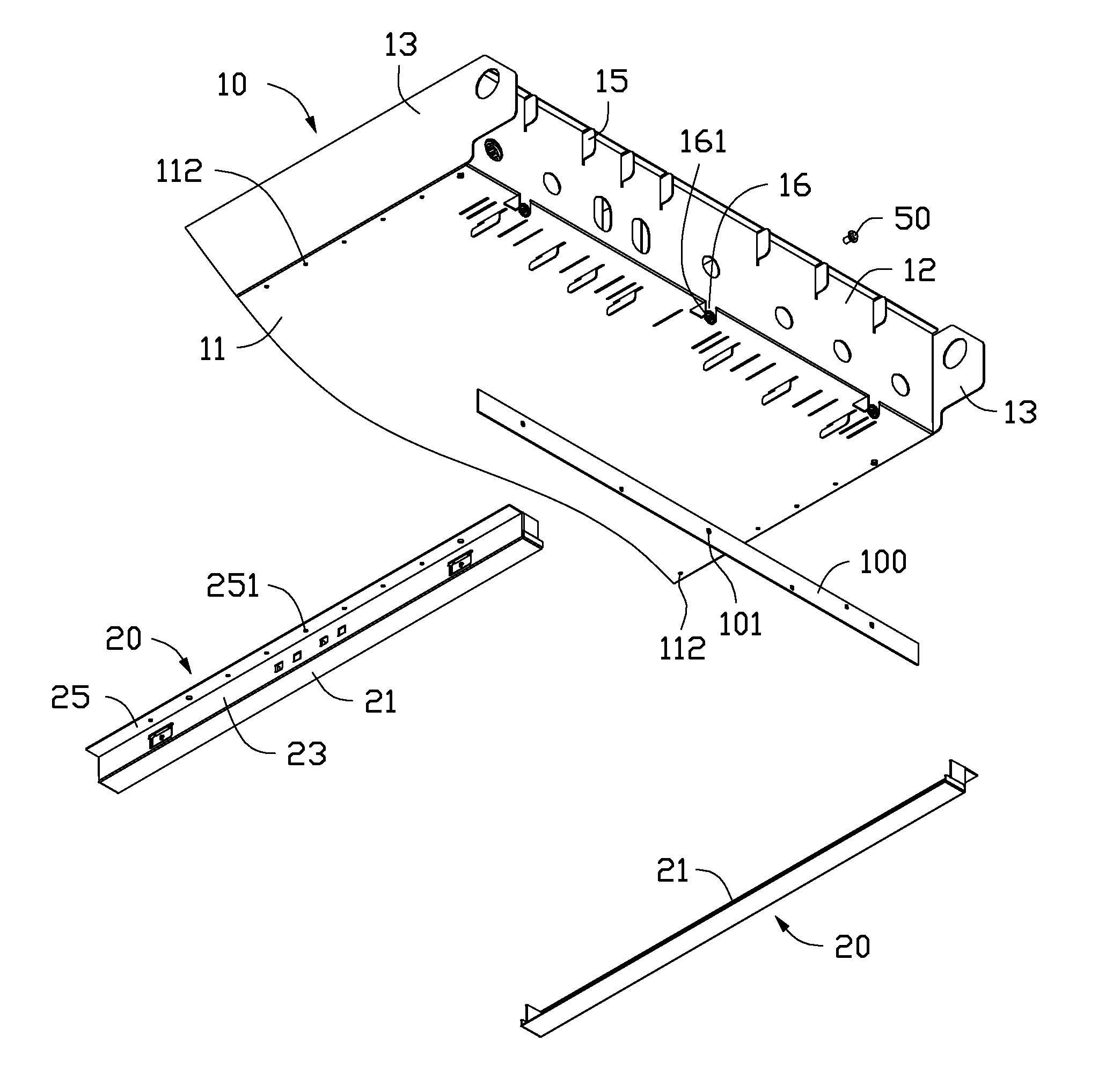
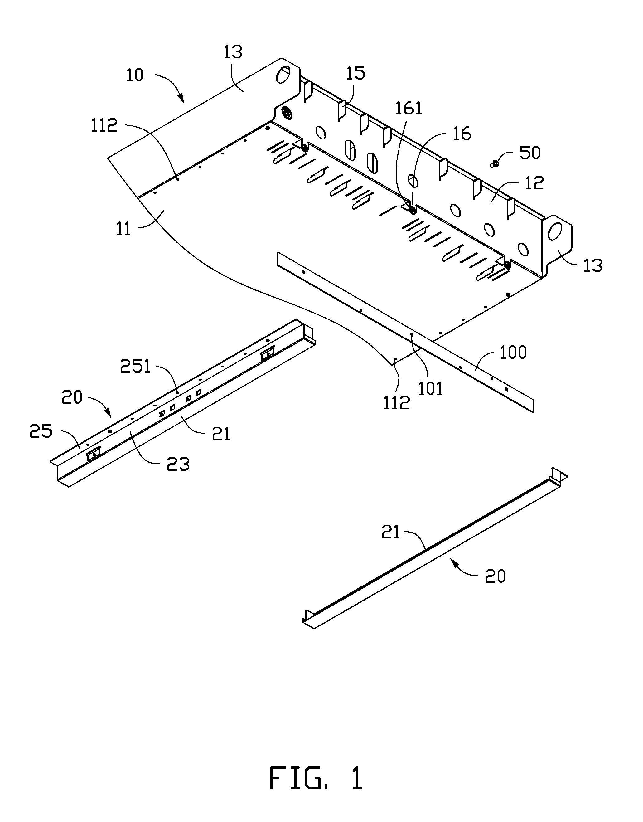
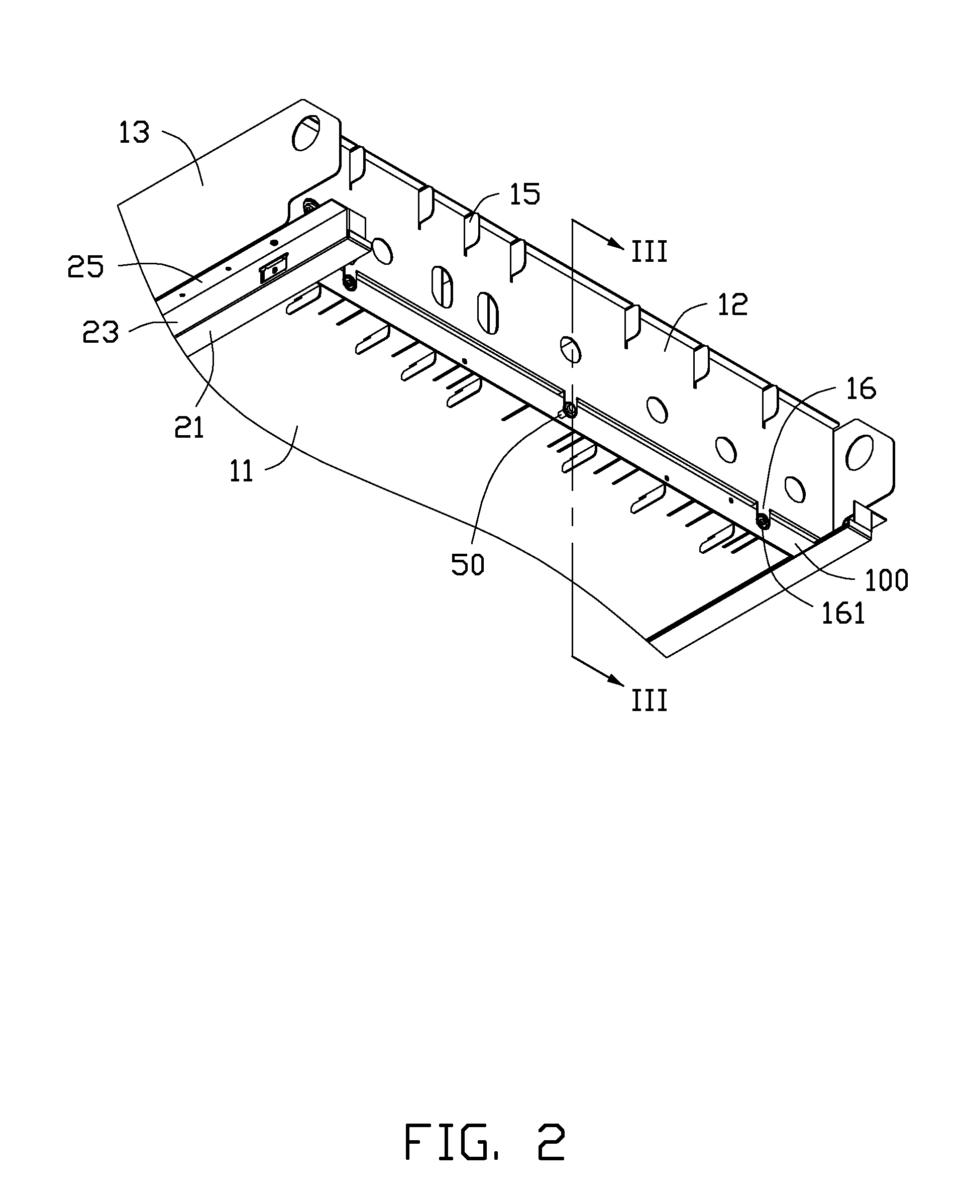
[0010]FIG. 1 shows one embodiment of a mounting device for securing an installation plate 100. The installation plate 100 is used for securing a plurality of motors (not shown) and defines a plurality of installation holes 101. The mounting device includes a chassis 10 and two brackets 20. In one embodiment, the chassis 10 is a product tray for placing product in a vending machine.

[0011]The chassis 10 includes a bottom plate 11, a front plate 12, and two side plates 13. The two side plates 13 are opposite to each other. In this embodiment, the bottom plate 11 is substantially perpendicular to the front plate 12 and the side plates 13, and the f...


PUM


Abstract

A mounting device includes an installation plate for securing a motor, a chassis, a bracket, and a locking member. The chassis includes a locking piece. The bracket is secured to the chassis. The bracket holds the installation plate. The locking member is locked into the installation plate and the locking piece, to secure the installation plate to the chassis without setting rivets in the installation plate.

Description

BACKGROUND[0001]1. Technical Field[0002]The present disclosure relates to a vending machine, and particularly to a mounting device for an installation plate for mounting a motor in the vending machine.[0003]2. Description of Related Art[0004]In many vending machines, the dispensing assembly includes rigid coils and motors. The motor rotates the coil causing products to be pushed along a channel to eventually drop into a bin accessible by a customer. The motor is secured to a tray of the vending machines by a installation plate. Generally, the installation plate is secured to a flange of the tray, which needs a number of rivets, and the installation plate is secured to flange by a number of screws into the rivets. However, the securing process of the installation plate is time-consuming, and a structure of the flange is complicated and costly. Therefore, there is room for improvement in the art.BRIEF DESCRIPTION OF THE DRAWINGS[0005]Many aspects of the embodiments can be better under...

Claims


Application Information

Patent Timeline
Patent Type & Authority Applications(United States)
IPC IPC(8): F16M13/02
CPCF16M13/02G07F11/42
Inventor CHEN, YUN-LUNGYEH, CHIN-WEN
Owner HON HAI PRECISION IND CO LTD
Learn More