Terminal apparatus, terminal apparatus controlling method, and control program

a terminal apparatus and control method technology, applied in the direction of television systems, coupling device connections, instruments, etc., can solve the problems of host devices, failure to eliminate the above-mentioned disadvantage, complex and costly structure, etc., and achieve the effect of minimizing the amount of power being dissipated from the battery

Inactive Publication Date: 2013-04-02
SONY CORP
View PDF7 Cites 3 Cited by
  • Summary
  • Abstract
  • Description
  • Claims
  • Application Information

AI Technical Summary

Benefits of technology

[0017]However, the proposed solution involving separately furnishing the additional control unit operating at the 100 mA current has the disadvantage of having a complicated and costly structure.
[0024]When the current of only up to 100 mA can be acquired from the host device according to the USB standard, as is the case immediately after power-up, the inventive terminal apparatus is configured to operate on the power from the battery. This makes it possible for the terminal apparatus to operate at the current of only up to 100 mA available from the host device without furnishing an additional control unit operating at the current of up to 100 mA.
[0025]Furthermore, when the current necessary for operating the relevant components of the terminal apparatus is requested of and made available from the host device, the terminal apparatus of the embodiment of the present invention can operate on the power derived from the host device alone. This translates into minimizing the amount of the power being dissipated from the battery. That in turn makes it possible to circumvent the situation in which the power falls short during communication with the host device.
[0028]According to the embodiments of the present invention, the terminal apparatus designed as a self-powered device under the USB standard is configured to notify its host device that it is a bus-powered device, thereby requesting VBUS currents of up to 500 mA from the host. When the current of only up to 100 mA is made available from the host device, as is the case immediately after power-up, the inventive terminal apparatus is configured to operate on the power from its battery. This makes it possible for the terminal apparatus to operate at the current of only up to 100 mA available from the host device without furnishing an additional control unit operating at the current of up to 100 mA. Furthermore, when the current necessary for operating the relevant components of the terminal apparatus is requested of and acquired from the host device, the power available from the host device alone is sufficient for operating the relevant components. This translates into minimizing the amount of the power being dissipated from the battery. That in turn makes it possible to circumvent the situation in which the power falls short during communication with the host device. In this manner, the embodiments of the present invention provides a terminal apparatus, a terminal apparatus controlling method and a control program, the terminal apparatus being simply structured but designed to ensure reliable communication with the host device from which power is supplied.

Problems solved by technology

However, the proposed solution involving separately furnishing the additional control unit operating at the 100 mA current has the disadvantage of having a complicated and costly structure.
This, however, fails to eliminate the above-mentioned disadvantage because the battery power is continuously dissipated.
However, this design not in compliance with the USB standard can adversely affect the host device and the USB communication protocol, so that reliable communication cannot be guaranteed.
As described above, the traditional terminal apparatus, when simply structured and designed as an Sp device, has had difficulty in reliably communicating with the host device.

Method used


Image

  • Terminal apparatus, terminal apparatus controlling method, and control program
  • Terminal apparatus, terminal apparatus controlling method, and control program
  • Terminal apparatus, terminal apparatus controlling method, and control program

Examples


first embodiment

1. First Embodiment

1-1. Overview of the First Embodiment

[0051]The first embodiment of the present invention is outlined below. The description of the overview of the first embodiment will be followed by an explanation of a specific example of the first embodiment.

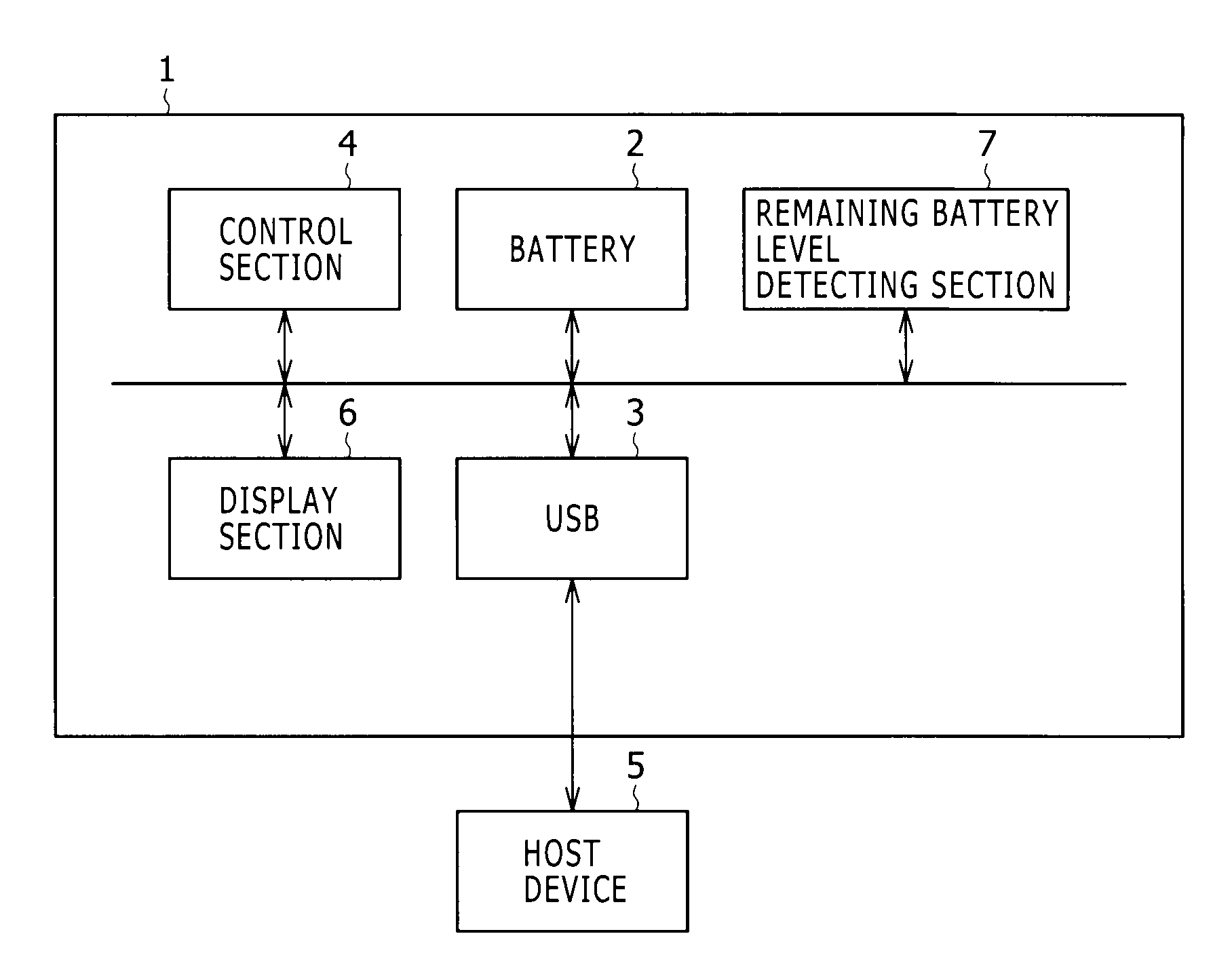
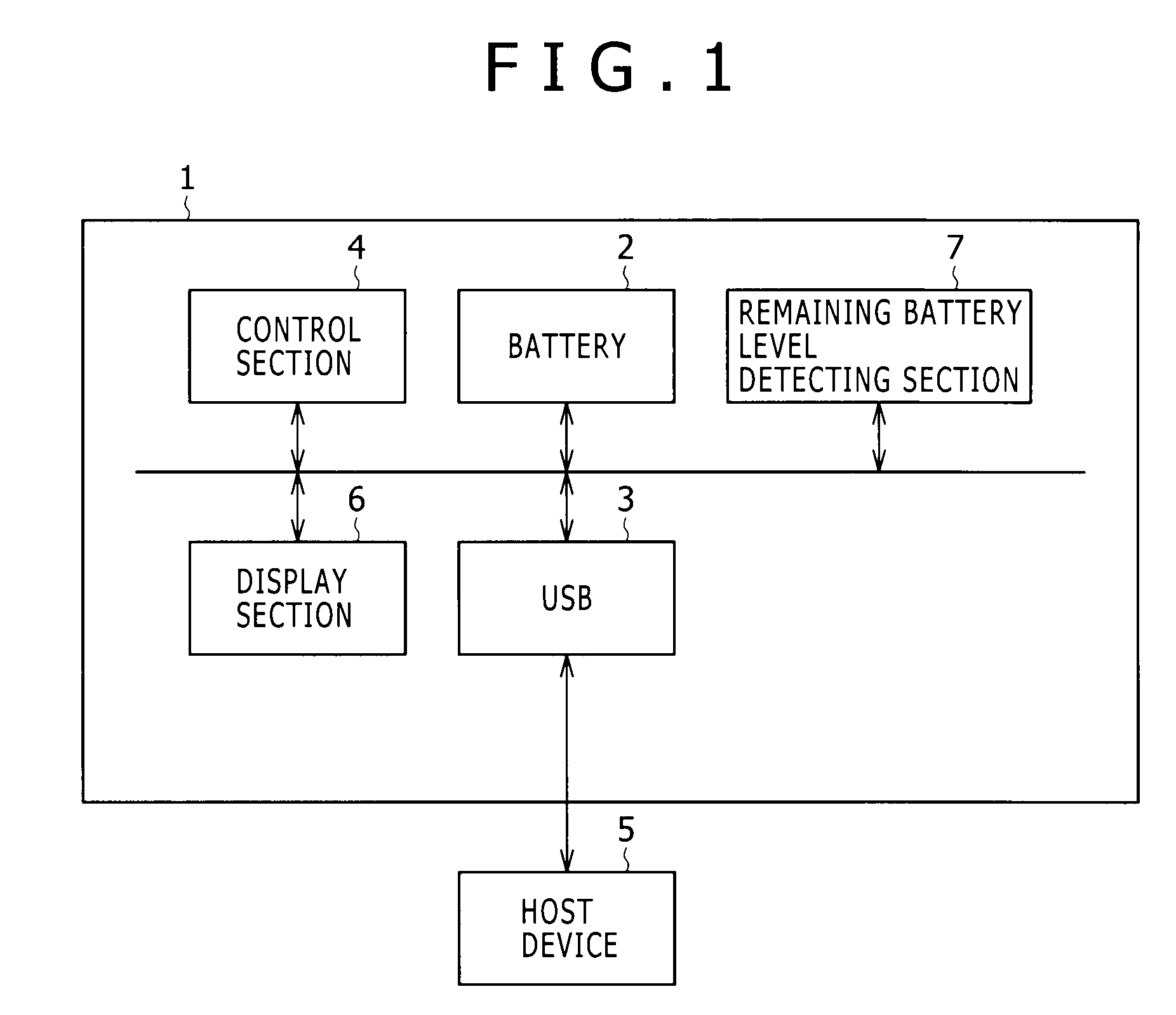
[0052]In FIG. 1, reference numeral 1 stands for a terminal apparatus practiced as the first embodiment of the present invention. The terminal apparatus 1 includes a battery 2, a USB port 3, and a control section 4.

[0053]The battery 2 is typically a detachable battery that supplies power necessary for operating the terminal apparatus 1. The USB port 3 provides an interface between the terminal apparatus 1 and a host device 5. As such, the USE port 3 permits communication with the host device 5 and ensures the supply of power from the host.

[0054]Upon power-up, the control section 4 causes relevant components of the terminal apparatus 1 to operate on the power from the battery 2. Thereafter, if the terminal apparatus 1 is conn...

second embodiment

2. Second Embodiment

[0155]The second embodiment of the present invention is described below. The above-described first embodiment was based on the assumption that the PC 34 is a host device capable of supplying the VBUS current of 500 mA. In reality, however, some PCs 34 are incapable of supplying the VBUS current of 500 mA. Requesting this type of PC 34 to supply the VBUS current of 500 mA fails to secure authorization to draw the current. As a result, the DSC 20 cannot start communicating with the PC 34.

[0156]When requesting the PC 34 to provide the VBUS current of 500 mA fails to secure authorization to tap the current, the second embodiment changes the request to circumvent the situation in which communication cannot be started with the PC 34.

[0157]Thus what follows is a description of the processing routine performed on the side of the DSC 20 when the DSC 20 and the PC 34 are connected (the routine is also called the connecting routine on the side of the DSC). The structure of ...

third embodiment

3. Third Embodiment

[0182]The third embodiment of the present invention is described below. The third embodiment changes the contents of the configuration descriptor to be sent back to the PC 34 in accordance with the remaining battery level of the battery 54.

[0183]Thus what follows is a description of the connecting routine performed on the side of the DSC 20 when the DSC 20 and the PC 34 are connected. The structure of the DSC 20 and that of the PC 34 are the same as those of the first embodiment, so that reference to the first embodiment may be made as needed with regard to the structures.

3-1. Connecting Routine on the Side of the DSC

[0184]FIG. 13 shows the connecting routine RT2 on the side of the DSC. The DSC-side connecting routine RT2 is primarily made up of steps carried out by the CPU 41 of the DSC 20.

[0185]In step SP200, the DSC 20 is turned on illustratively by the user's operation. At this point, the power managing section 49 of the DSC 20 sets the battery 54 as the power...


PUM


Abstract

Disclosed herein is a terminal apparatus designed as a self-powered device according to the Universal Serial Bus standard, the terminal apparatus including: a battery; a USB port; and a control section configured to allow relevant components of the terminal apparatus to operate on power from the battery upon power-up, the control section further notifying a host device upon connection thereto through the USB port that the terminal apparatus is a bus-powered device, in order to request a current necessary for the relevant components to operate only on the power supplied from the host device to the bus-powered device.

Description

BACKGROUND OF THE INVENTION[0001]1. Field of the Invention[0002]The present invention relates to a terminal apparatus, a terminal apparatus controlling method, and a control program. More particularly, the invention relates to a terminal apparatus connected to a host device illustratively through a USB port.[0003]2. Description of the Related Art[0004]In recent years, many terminal apparatuses including digital still cameras and digital audio players have adopted the USB (Universal Serial Bus) as the interface for connecting with other devices.[0005]With recording media getting ever larger in capacity, the above-mentioned type of terminal apparatus connected with a host device through a USB port has an increasing number of files to be exchanged with the latter. The result is a tendency toward prolonged connection time for the devices involved.[0006]The above type of terminal apparatus contains a battery. While being connected with the host device, the terminal apparatus keeps consum...

Claims


Application Information

Patent Timeline
Patent Type & Authority Patents(United States)
IPC IPC(8): G06F1/26G06F1/32
CPCG06F1/266H04N1/00901H04N5/23203H04N5/23241H04N1/00204H04N2201/001H04N2201/0049H04N2201/0084H04N23/66H04N23/65
Inventor NAKAYAMA, TETSUNORI
Owner SONY CORP
Why Eureka
Try Eureka