Fixing device

Active Publication Date: 2014-07-03
CANON KK
View PDF3 Cites 31 Cited by
  • Summary
  • Abstract
  • Description
  • Claims
  • Application Information

AI Technical Summary

Benefits of technology

[0013]A principal object of the present invention is to provide a fixing device capable of stably bringing a heater and a metal plate into contact

Problems solved by technology

When the heater causes abnormal temperature rise, the electric power supply to the heater is blocked by the fuse or a thermostat.
Here, as one of problems in the above-described fixing device, there is heater breaking (cracking) due to thermal runaway.
The cause of this heater breaking includes thermal stress resulting from generation of a difference in temperature of the heater and generation of mechanical stress, exerted on the heater, by partial melting of the supporting member.
However, in recent years, demands for shortening of FPOT (first page out time) and improvement in

Method used


Image

  • Fixing device
  • Fixing device
  • Fixing device

Examples


embodiment 1

[0042]In the following description of a device structure, a direction refers to a direction perpendicular to a recording material feeding direction in a recording material feeding path. A widthwise direction is the same direction as the recording material feeding direction.

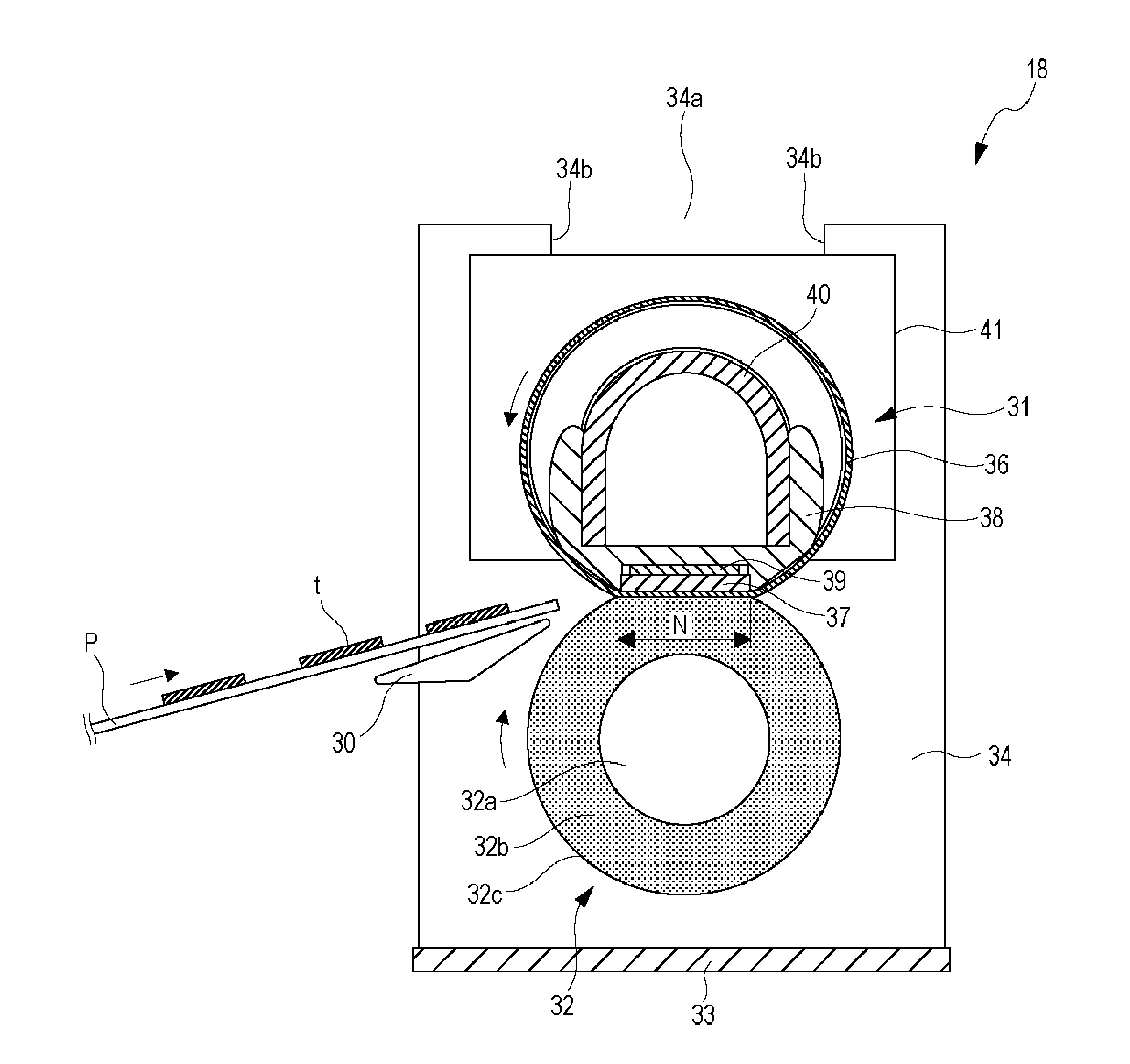
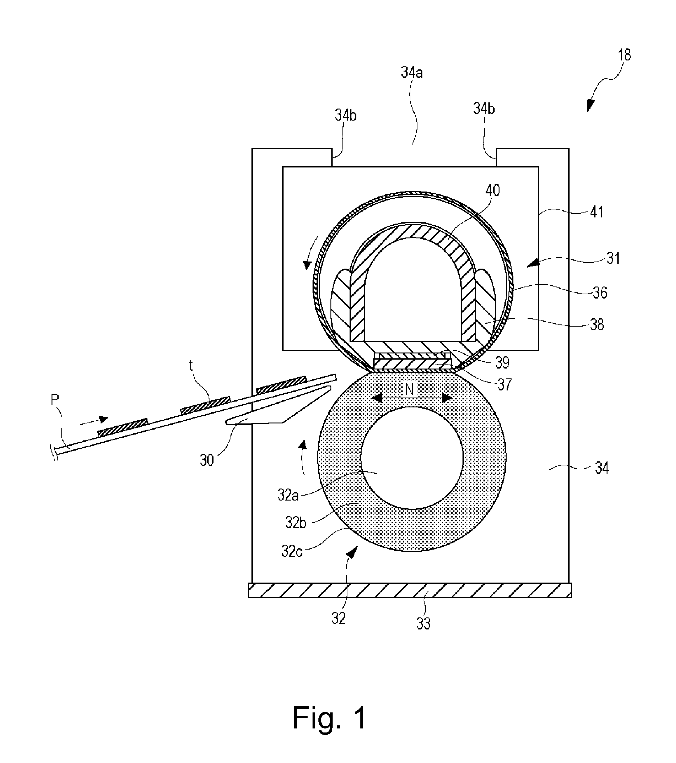
[0043]FIG. 1 is a schematic sectional view of a fixing device 18 in this embodiment as seen from the longitudinal direction of the fixing device 18, and FIG. 2 is a schematic view of the fixing device 18 as seen from the widthwise direction at an end portion of the fixing device 18.

[0044]The fixing device 18 includes a film unit 31 including a cylindrical film 36 having flexibility and includes a pressing roller 32 as a pressing member. The film unit 31 and the pressing roller 32 are provided in substantially parallel to each other between left and right side plates 34 of a device frame 33.

[0045]The pressing roller 32 includes a core metal 32a, an elastic layer 32b formed outside the core metal 32a, and a parting ...

embodiment 2

[0086]In this embodiment, different from Embodiment 1 in which the crown shape is provided at the supporting surface of the supporting member 38, a constitution in which the crown shape is provided at an opposing surface, of the metal plate 39, to the heater 37 is employed. The metal plate 39 is, similarly as in Embodiment 1, constituted by aluminum. A difference between this embodiment and Embodiment 1 is only the supporting member 38 and the metal plate 39, and other constitutions are substantially the same as those in Embodiment 1 and therefore will be omitted.

[0087]A feature of this embodiment will be described. The metal plate 39 has, as shown in FIG. 9, a shape such that a central portion thereof with respect to the generatrix direction of the film 36 is projected more than end portions in a direction in which the metal plate 39 approaches the heater 37. The metal plate 39 has a crown shape which is a moderately curved shape such that the metal plate 39 gradually approaches th...

embodiment 3

[0092]A fixing device 18 according to this embodiment is the same as the fixing device 18 in Embodiment 1 except for a heat conduction member 39 and a supporting member 38 and therefore will be omitted from description. With reference to FIG. 5, the heat conduction member 39 in this embodiment will be described.

[0093]The heat conduction member 39 is formed with an aluminum plate. Part (a) of FIG. 13 is a sectional view of an assembly of the supporting member 38 with the heat conduction member 39 and the heater 37 as seen from a widthwise direction, (b) of FIG. 13 is a sectional view of the assembly of (a) of FIG. 13 from which the electric power supplying connector 46 and the heater clip 47 are omitted from illustration, (c) of FIG. 13 is a top (plan) view of the assembly of the supporting member 38 with the heat conduction member 39, and (d) of FIG. 13 is a perspective view of the supporting member 38 and the heat conduction member 39.

[0094]In this embodiment, as shown in (a) of FI...


PUM


Abstract

A fixing device includes a cylindrical film, a planar heater, a heat conduction member, a supporting member, a limiting member for limiting heater end portions with respect to a generatrix direction of the film so as to prevent the end portions from moving in a heater thickness direction relative to the supporting member, and a pressing member. A fixing device state is switchable between a first state in which a press-contact force in the nip is enough to fix the toner image and a second state in which the press-contact force in the nip is smaller than the press-contact force in the first state. A surface where the supporting member opposes the heat conduction member has a shape such that with respect to the generatrix direction, a central portion of the film is projected toward the pressing member than an end portion of the film.

Description

FIELD OF THE INVENTION AND RELATED ART[0001]The present invention relates to a fixing device for use with an image forming apparatus, such as a copying machine or a printer, of an electrophotographic type.[0002]In recent years, as a type of the fixing device provided in the image forming apparatus of the electrophotographic type, a film fixing type has been used. The fixing device of the film fixing type generally has a constitution including a cylindrical film, a heater contacting an inner surface of the film, a supporting member for supporting the heater at an opposing surface to a surface where the heater contacts the inner surface of the film, and a pressing member for forming a nip, together with the heater, between the pressing member and the film. Further, the fixing device heats a recording material on which a toner image is carried while feeding the recording material through the nip, thus fixing the toner image on the recording material.[0003]As the heater, a heater prepar...

Claims


Application Information

Patent Timeline
IPC IPC(8): G03G15/20
CPCG03G15/2053G03G15/2064G03G15/206G03G15/2014G03G15/2017G03G15/2003G03G2215/2035G03G15/2057
Inventor IMAIZUMI, TORUNARAHARA, TAKASHIANDO, ATSUTOSHIMINAMISHIMA, YASUHITOTATEISHI, TOMOYAMAEDA, MASAFUMI
Owner CANON KK
Why Eureka
Try Eureka