
Apparatus and Method for Forming a Screw Flight

Active Publication Date: 2014-07-17
ADVANCED SPIRAL TECH
View PDF7 Cites 1 Cited by
  • Summary
  • Abstract
  • Description
  • Claims
  • Application Information

AI Technical Summary

Benefits of technology

The patent describes a method for making a flight blank, which is a circular piece of fabric used in flight suits. The method involves twisting the fabric around its central axis, which prevents it from getting bent or rolled across its own cross-section. This results in a more complete and accurate fit of the fabric to the wearer's body. This "technical effect" in the manufacturing process improves the performance and comfort of flight suits.

Problems solved by technology

These disadvantages include that, depending on the thickness of the blank material used, is it often necessary to repeat the die pressing operation several times in order to conform the shape of the annulus to the shape of the dies between which the blank is pressed.
The requirement to repeat the pressing cycle necessarily adds to the costs of production of screw flights produced via this method.
Furthermore, the blank typically undergoes plastic deformation during the pressing process which can lead to inaccuracy in flight profiles outside of desired manufacturing tolerances.
Such variations away froth desired manufacturing tolerances necessarily lead to inferior products and a resulting reduction in product performance and lifespan.
In addition, for each particular size and pitch for a flight, two sets of dies are needed if both left and right hand flights are to be produced, further adding to the costs of using dies to form screw flights.
It is also difficult to produce accurate dies which will produce a flight of a particular size and pitch.

Method used


Image

  • Apparatus and Method for Forming a Screw Flight
  • Apparatus and Method for Forming a Screw Flight
  • Apparatus and Method for Forming a Screw Flight

Examples


Embodiment Construction

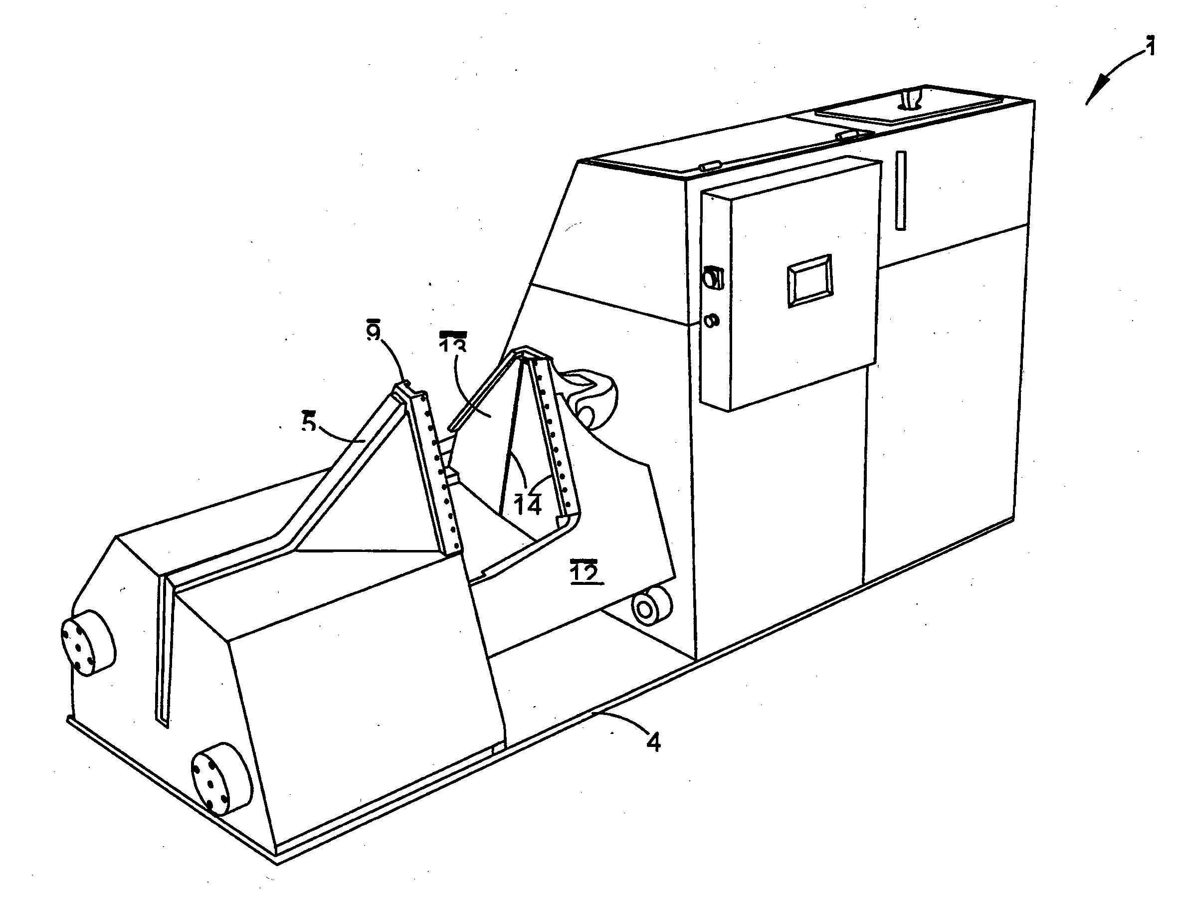
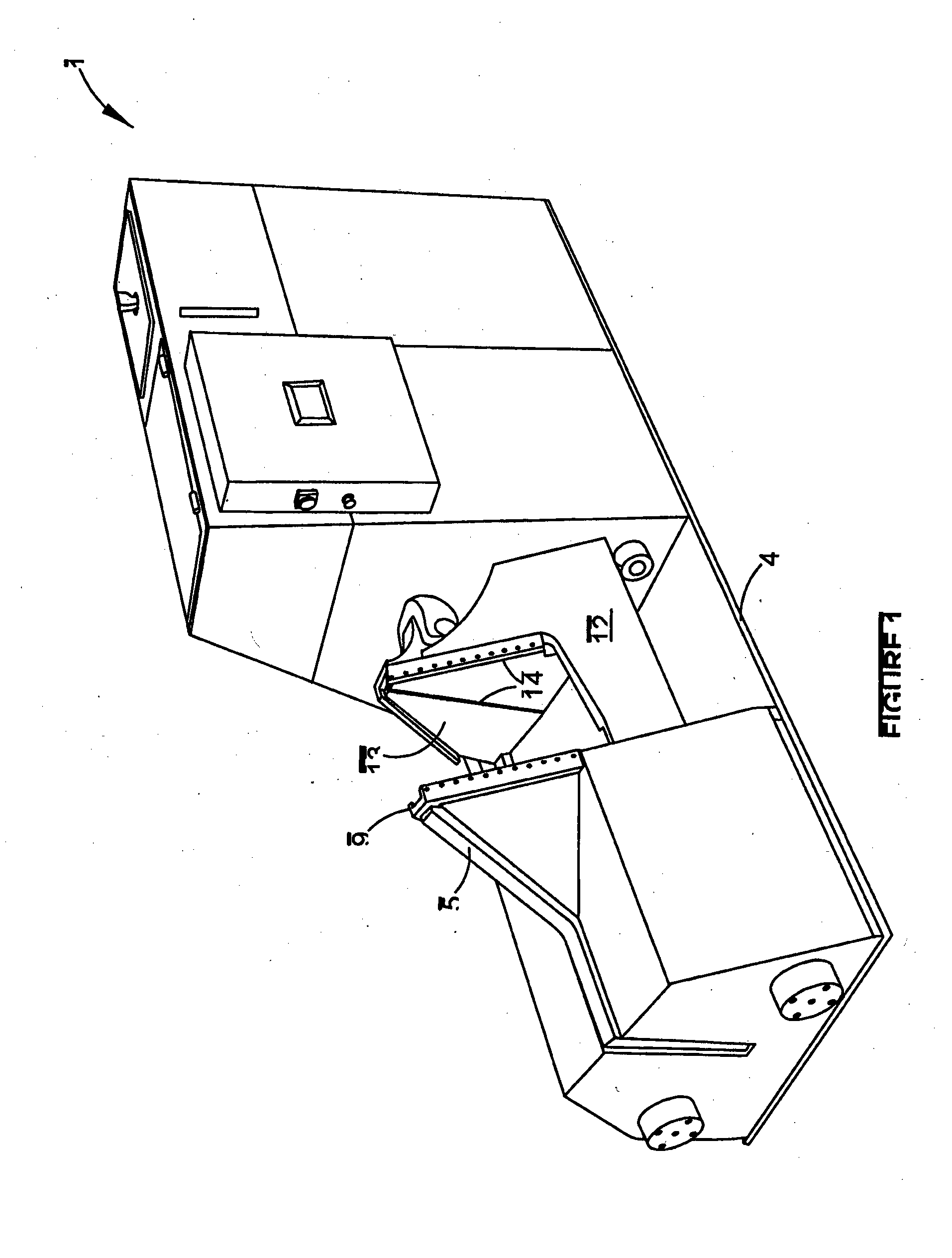
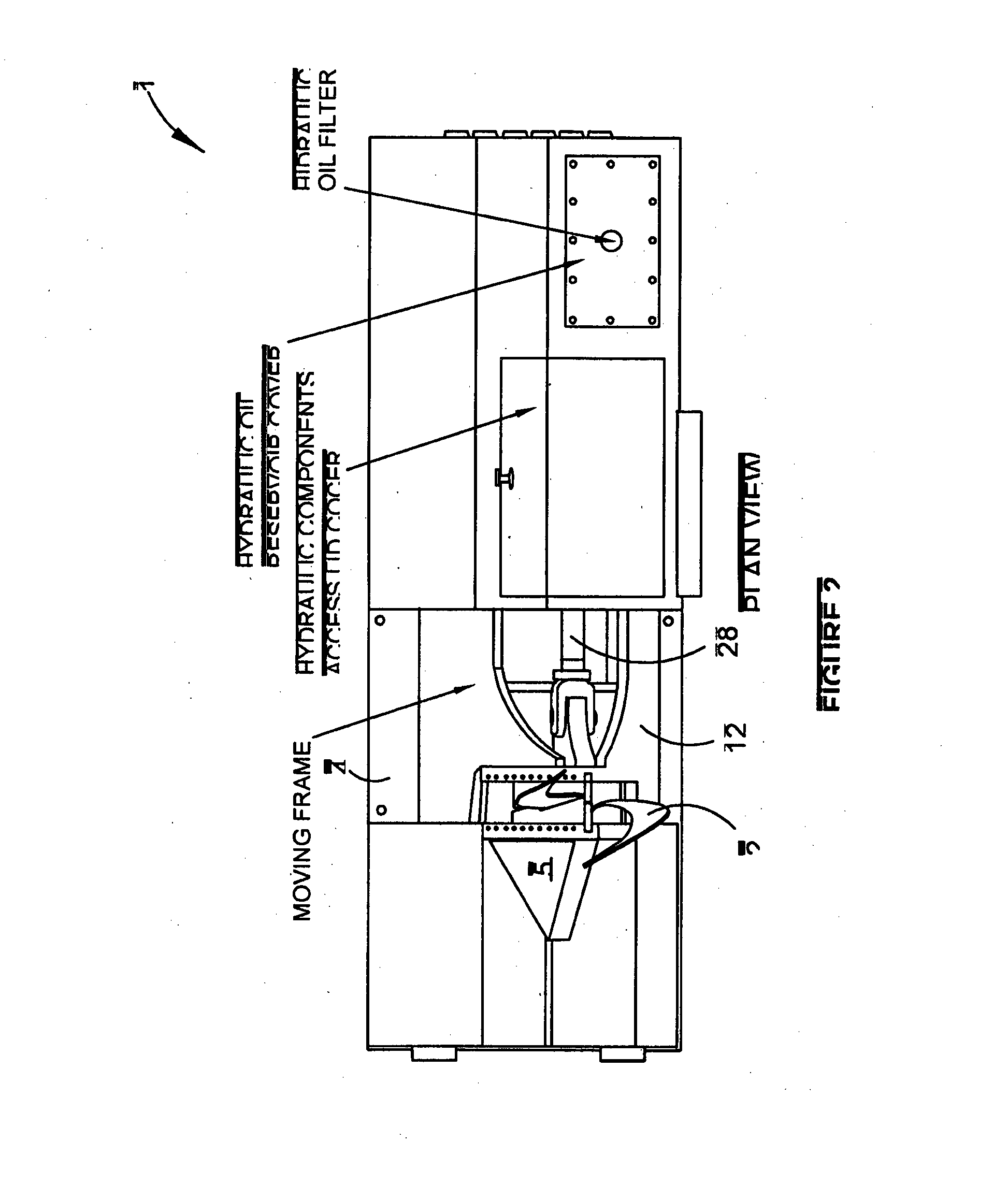
[0070]Referring to the drawings, the invention provides an apparatus 1 for forming a helical screw flight 2 from an open ended annulus shaped flight blank 3. As most clearly shown in FIG. 6, the annulus shaped blank 3 has an inner diameter and an outer diameter.

[0071]The size of the blank 3 is calculated from the values of the desired properties of the helical flight 2 including the inner and outer diameters of the flight 2, the pitch of the flight (FIG. 7) and the thickness of the material used to form the blank / flight (FIG. 8). It will be appreciated by those skilled in the art that the inner and outer diameters of the blank 3 are necessarily greater than those of the formed flight 2.

[0072]The flight forming apparatus 1 has a base 4 for resting the apparatus 1 on a supporting surface such as a workshop floor (not shown).

[0073]The apparatus 1 includes a mounting means in the form of a mounting frame 5 fixedly connected to the base 4. The fixed mounting frame 5 is configured for mou...


PUM

PropertyMeasurementUnit
Sizeaaaaaaaaaa
Radiusaaaaaaaaaa
Distanceaaaaaaaaaa

Abstract

This invention relates to an apparatus for forming a helical screw flight from a flight blank. The apparatus includes a base and an engaging means. The engaging means is movably mounted to the base and is configured to formingly engage the blank so as to form a twist in at least a portion of the flight blank corresponding to a predetermined pitch of the flight.

Description

FIELD OF THE INVENTION[0001]This invention relates generally to the field of materials handling equipment. More particularly, the present invention relates to screw or auger flights (particularly sectional flights) and to an apparatus and method of forming such flights.BACKGROUND OF THE INVENTION[0002]Any discussion of the prior art throughout the specification should in no way be considered as an admission that such prior art is widely known or forms part of common general knowledge in the field.[0003]Screw or auger flights are typically used in bulk handling industries for efficiently moving fluid, granular or semi-solid material. Rotation of the flight causes the material to be conveyed along the surface of a spiralled coil section.[0004]The means and method of manufacturing conventional sectional screw flights involves pressing each section of flight between a set of appropriately shaped dies. Each section of flight is then typically welded to a shaft in sequence to form a compl...

Claims


Application Information

Patent Timeline
IPC IPC(8): B21D11/14
CPCB21D11/14B21D11/06B21D11/07
Inventor BLOXHAM, GREGORY, JOHN
Owner ADVANCED SPIRAL TECH
Learn More