Vibration generator moving vibrator by magnetic field generated by coil and vibrator-mounted holder used in vibration-generator

a technology of vibration generator and magnetic field, which is applied in the direction of mechanical vibration separation, magnetic circuit shape/form/construction, instruments, etc., can solve the problems of increasing the number of parts, increasing the manufacturing cost of the vibration generator, and complicated structure of the attachment unit for attaching the plate spring to the chassis

Active Publication Date: 2014-07-24
MINEBEAMITSUMI INC
View PDF5 Cites 19 Cited by
  • Summary
  • Abstract
  • Description
  • Claims
  • Application Information

AI Technical Summary

Problems solved by technology

Therefore, the structure of an attachment unit for attaching the plate spring to the chassis is complicated.
Therefore, the steps of assembling the vibration generator are complicated, the number of parts increases, and the manufacturing cost of the vibration generator increases.
Such a problem becomes more serious as the demand for smaller and a thinner vibration generator increases.
There...

Method used


Image

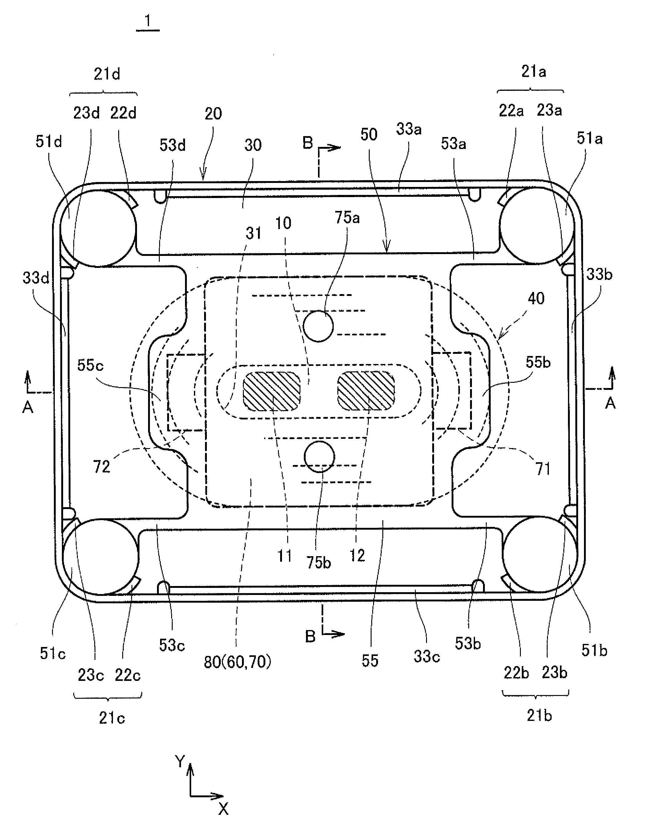
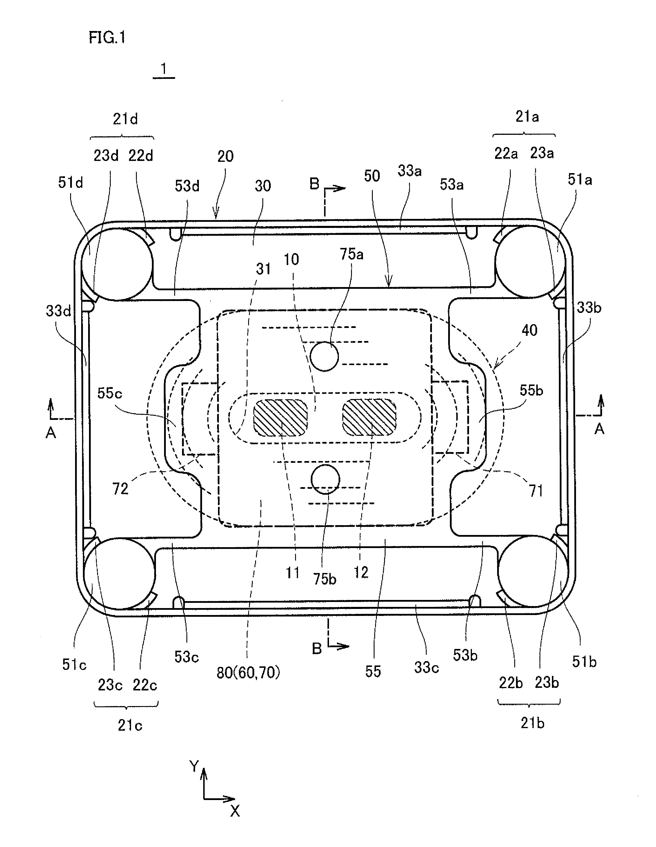
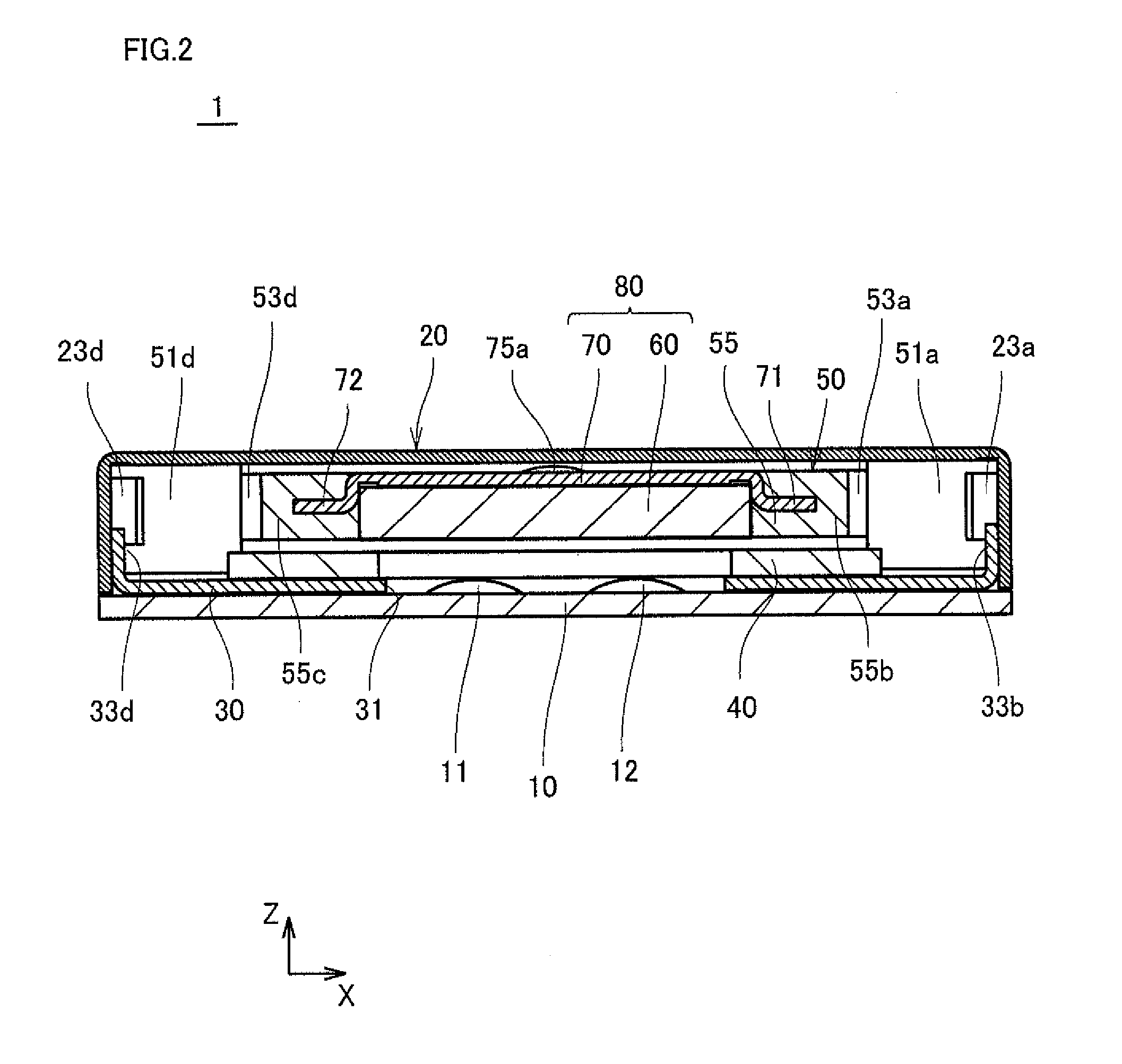
  • Vibration generator moving vibrator by magnetic field generated by coil and vibrator-mounted holder used in vibration-generator
  • Vibration generator moving vibrator by magnetic field generated by coil and vibrator-mounted holder used in vibration-generator
  • Vibration generator moving vibrator by magnetic field generated by coil and vibrator-mounted holder used in vibration-generator

Examples


first embodiment

Modification of First Embodiment

[0088]Vibration generator 1 may include a substrate and a bottom plate having a structure different from double-sided substrate 10 and bottom plate 30 instead of double-sided substrate 10 and bottom plate 30.

[0089]FIG. 7 is a development view illustrating a substrate 210 and a bottom plate 230 according to one modification of the first embodiment.

[0090]Substrate 210 is a Flexible Printed Circuit board (FPC), and is arranged in such a manner that bottom plate 230 is inserted in substrate 210. In other words, substrate 210 is arranged to partially cover both surfaces of bottom plate 230. In FIG.

[0091]7, substrate 210 is expanded in the form of plane.

[0092]Bottom plate 230 has a flat plate shape. Bottom plate 230 is inserted from the bottom side of frame 20, and fixed to frame 20. Referring to FIG. 7, a notch portion 235 is provided in a portion (an example of a portion of an edge portion) located in an upper portion among edge portions of bottom plate 2...

second embodiment

Modification of Second Embodiment

[0126]FIG. 16 is an exploded perspective view illustrating a vibrator-mounted holder of a vibration generator according a first modification of the second embodiment. FIG. 17 is a perspective view illustrating the vibrator-mounted holder.

[0127]As illustrated in FIG. 16, in the present modification, a vibrator 1380 and a holder 1350 which are thick in an up-and-down direction and which are slightly large are used. In the present modification, holder 1350 is divided into four pieces and each piece includes a pillar body 1351 (1351a to 1351d), an arm 1353 (1353a to 1353d) constituted by two beams, and a retention unit 1355 (1355a to 1355d). Four retention units 1355 retain a weight 1381 with an end portion of a weight 1381 interposed between two retention units 1355 adjacent to each other. For example, as for retention unit 1355a, weight 1381 is retained such that weight 1381 is interposed between retention unit 1355a and retention unit 1355b and betwee...


PUM


Abstract

A vibrator-mounted holder is attached to a casing of a vibration generator which moves a vibrator to generate a vibration when used. The vibrator-mounted holder includes a vibrator, a vibrator retention unit retaining the vibrator, a fixing unit fixed to a casing, and an arm. The vibrator includes a magnet having a plate shape parallel to a horizontal surface and a yoke arranged on the magnet. The arm connects the fixing unit to the vibrator retention unit, and supports the vibrator retention unit in a manner that the vibrator retention unit is displaceable with respect to the fixing unit. The yoke has a projecting portion which is projected downward and fixed to the vibrator retention unit. The arm is connected to a portion, at which the projecting portion is arranged, within the vibrator retention units.

Description

[0001]This application is based on Japanese Patent Application No. 2013-8961 filed with the Japan Patent Office on Jan. 22, 2013, the entire content of which is hereby incorporated by reference.BACKGROUND OF THE INVENTION[0002]1. Field of the Invention[0003]The present invention relates to a vibration generator, particularly to a vibration generator that moves a vibrator to generate a vibration by passage of a current through a coil.[0004]2. Description of the Related Art[0005]As a vibration generator that moves a vibrator to generate vibration, a variety of vibration generators are used which has a structure in which a vibrator including a magnet weight is supported by a chassis with a plate spring interposed. This vibration generator includes a coil arranged under the magnet. The coil is disposed opposite the magnet. The vibrator moves while deforming the spring, in conjunction with generation of a magnetic field induced by an electric current which flows through the coil.[0006]Do...

Claims


Application Information

Patent Timeline
IPC IPC(8): G01M7/02
CPCG01M7/027H02K33/16B06B1/045H02K1/34
Inventor UMEHARA, MIKIO
Owner MINEBEAMITSUMI INC
Why Eureka
Try Eureka