
Assembly process for glue-free hinge

a technology of glue-free hinges and assembly processes, which is applied in the direction of hinges, pinless hinges, door/window fittings, etc., can solve the problems of low strain on anodized components, prone to damage when placed under low strain, and prone to anodization cracking

Active Publication Date: 2014-08-07
APPLE INC
View PDF31 Cites 14 Cited by
  • Summary
  • Abstract
  • Description
  • Claims
  • Application Information

AI Technical Summary

Benefits of technology

The patent describes a method for using press fit technology to replace adhesive fittings in sensitive components. This allows for a smaller overall assembly, especially when the parts involved are sensitive to low levels of strain. The technical effect of this invention is to provide a safer and more efficient way to join anodized parts together, without compromising their quality.

Problems solved by technology

Anodized components can be susceptible to damage when placed under low levels of strain.
When a sufficient amount of strain is put on an anodized part a phenomenon called anodization cracking can occur.
Anodization cracking can occur when the underlying substrate of an anodized surface treatment experiences too much surface strain.
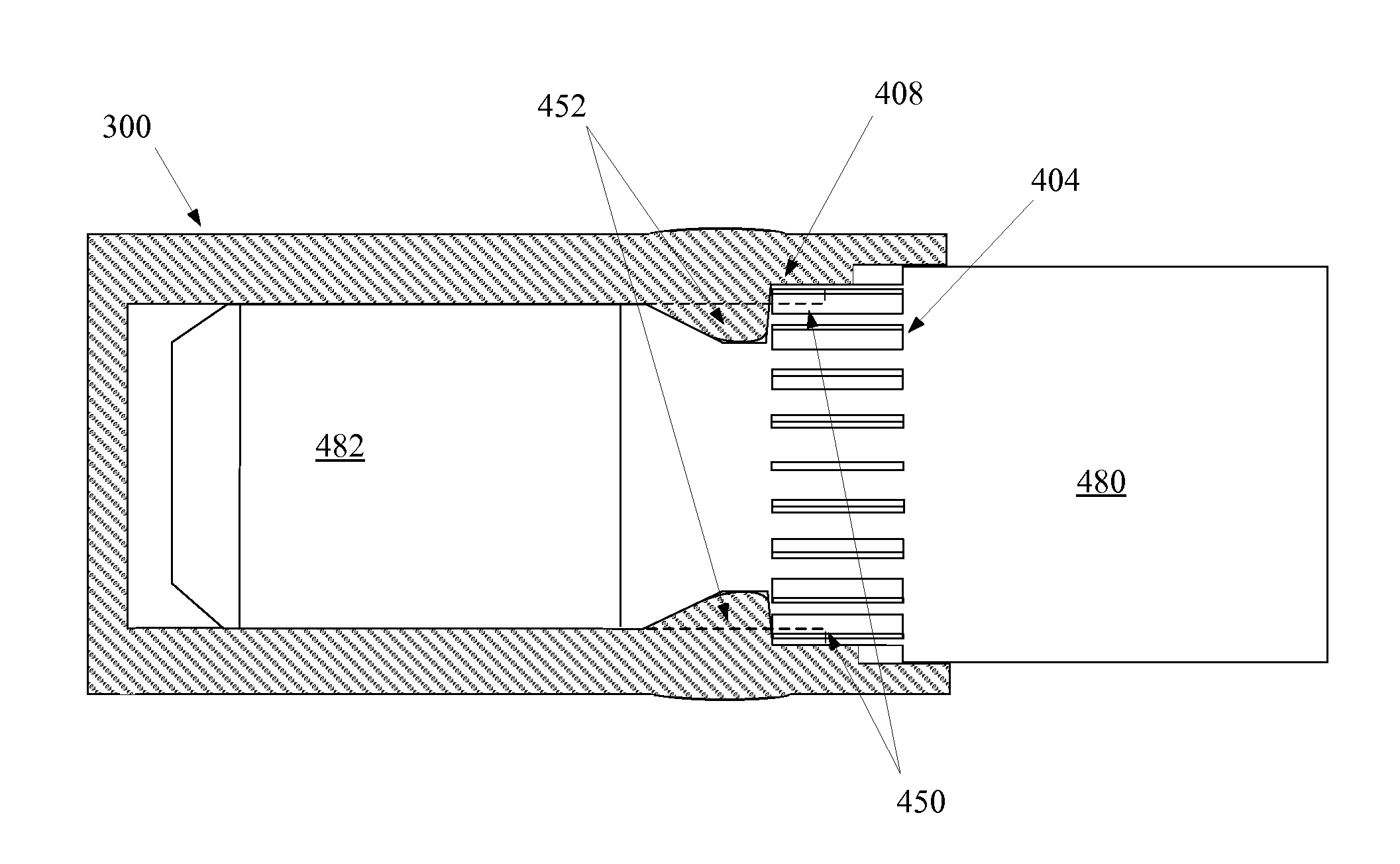
This surface strain can be caused in some cases by a press-fitting that exerts an undue amount of force on an interior portion of the underlying substrate, essentially causing bulging to occur on the exterior surface of that substrate.
Anodization cracking is quite obvious in an end product and generally manifests with a number of ghosting lines or splotches running along the areas where the cracking occurred.
Consequently, manufacturers of anodized parts have been justifiably cautious in employing technologies which put strain on anodized parts.
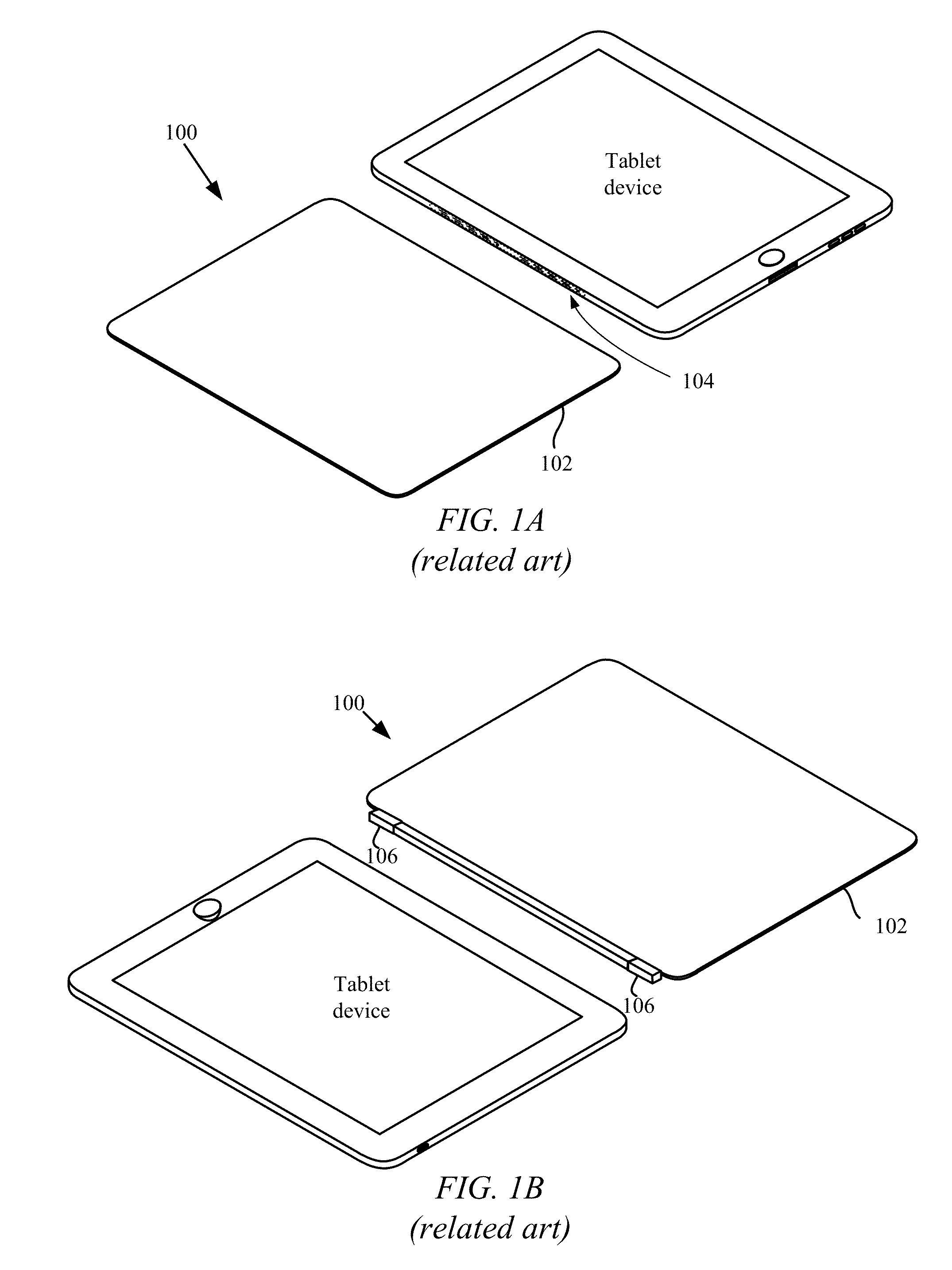
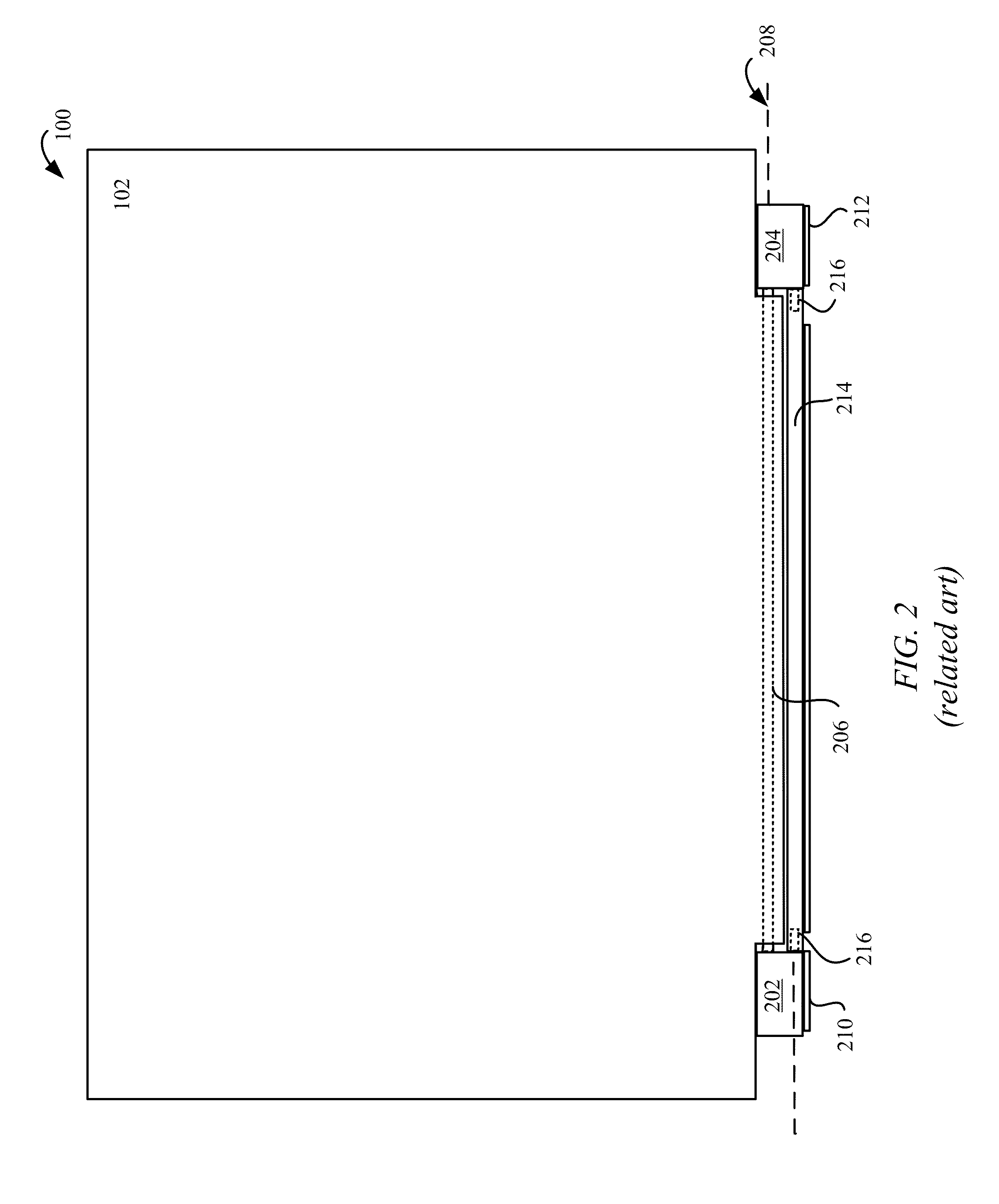
Unfortunately, the use of an adhesive when bonding a pin inside of a channel can result in large components due to the amount of surface area required to achieve a sufficiently strong connection as well as the added cost in time and efficiency in assembly and manufacturing.

Method used


Image

  • Assembly process for glue-free hinge
  • Assembly process for glue-free hinge
  • Assembly process for glue-free hinge

Examples


Embodiment Construction

[0023]A representative apparatus and application of methods according to the present application are described in this section. These examples are being provided solely to add context and aid in the understanding of the described embodiments. It will thus be apparent to one skilled in the art that the described embodiments may be practiced without some or all of these specific details. In other instances, well known process steps have not been described in detail in order to avoid unnecessarily obscuring the described embodiments. Other applications are possible, such that the following examples should not be taken as limiting.

[0024]In the following detailed description, references are made to the accompanying drawings, which form a part of the description and in which are shown, by way of illustration, specific embodiments in accordance with the described embodiments. Although these embodiments are described in sufficient detail to enable one skilled in the art to practice the desc...


PUM


Abstract

The described embodiment relates generally to the field of press-fit technology. Press-fit technology results in deformation of one component to lock another component in place. This deformation commonly causes surface strain to occur on the deforming component. When a component is anodized surface strain can result in anodization cracking; this ruins the finished appearance of cosmetic surfaces, generally resulting in ghosting lines and splotches appearing on the surface of a component. The described embodiment achieves a careful balance between component deformation and surface strain. By utilizing specific press-fit geometries and assembly methods, surface strain can be sufficiently limited to eliminate anodization cracking while also achieving a durable press-fit joint.

Description

CROSS-REFERENCE TO RELATED APPLICATION[0001]This application claims the benefit of priority from U.S. Provisional Patent Application No. 61 / 734,895, filed on Dec. 7, 2012, which is hereby incorporated herein by reference in its entity.BACKGROUND[0002]1. Technical Field[0003]The described embodiment relates generally to methods for employing press fit technology. More specifically, specially designed press fits can be used in place of adhesive based support fittings enabling a much smaller overall assembly even when the parts involved are sensitive to low levels of surface strain.[0004]2. Related Art[0005]Anodized components can be susceptible to damage when placed under low levels of strain. When a sufficient amount of strain is put on an anodized part a phenomenon called anodization cracking can occur. Anodization cracking can occur when the underlying substrate of an anodized surface treatment experiences too much surface strain. This surface strain can be caused in some cases by ...

Claims


Application Information

Patent Timeline
IPC IPC(8): E05D7/00
CPCE05D7/00E05Y2600/506E05D5/127
Inventor FRANKLIN, JEREMY C.LAUDER, ANDREW D.BENTRIM, BRIANZHU, ALAN
Owner APPLE INC
Learn More