Balustrade anchor post and balustrade installation method

a technology for installing balustrades and balustrades, which is applied in the field of balustrades, can solve the problems of wasting considerable time, and affecting the installation effect of balustrades,

Inactive Publication Date: 2014-08-07
GREEN ROBERT H
View PDF6 Cites 12 Cited by
  • Summary
  • Abstract
  • Description
  • Claims
  • Application Information

AI Technical Summary

Problems solved by technology

However the installation of metal balusters is more problematic than the installation of wood balusters and there remains room for improvement in this regard.
Conventional installation of metal balusters involves the use of epoxy resin which is time consuming, requires the handling of chemicals, and can be a messy pro

Method used


Image

  • Balustrade anchor post and balustrade installation method
  • Balustrade anchor post and balustrade installation method
  • Balustrade anchor post and balustrade installation method

Examples


Embodiment Construction

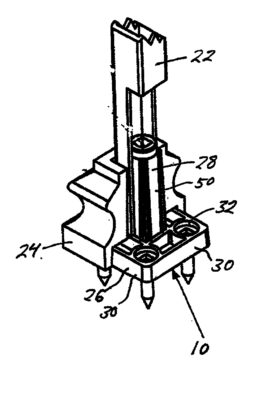
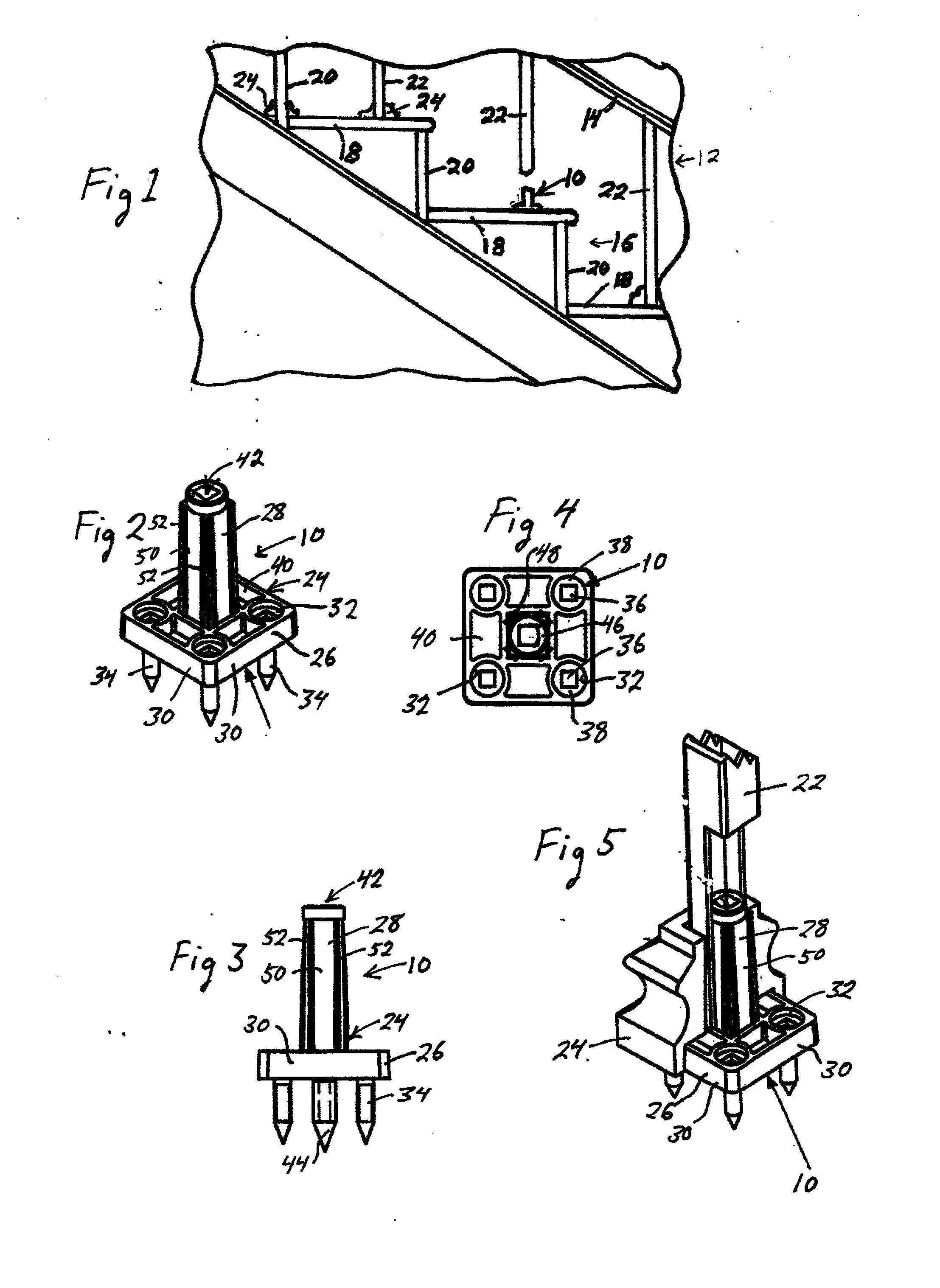
[0029]Now referring to FIG. 1, a preferred embodiment of a balustrade anchor post of the present invention is shown and indicated generally by the numeral 10. In FIG. 1 a plurality of anchor posts 10 are shown in use with a typical stair case balustrade indicated by the numeral 12. Except for the use of anchor posts 10 of the present invention, balustrade 12 is illustrated in FIG. 1 as comprising conventional components: hand rail 14 for staircase 16 which has stairway treads 18 and risers 20. Hand rail 14 is supported by a plurality of vertically extending, horizontally spaced, iron balusters 22 which are themselves anchored by anchor posts 10 secured to treads 18. The lower portion of each baluster 22 is covered by a decorative shoe 24 as is conventional in the art.

[0030]The details of anchor post 10 are shown in FIGS. 2-5. Anchor post 10 generally has a body 24 with a flange 26 having a projection 28 extending generally upwardly from flange 26 as viewed in the Figures.

[0031]Flang...


PUM

PropertyMeasurementUnit
Polymericaaaaaaaaaa

Abstract

An anchor post for mounting a baluster having a hollow interior. The anchor post has a body adapted to carry a fastening element for attaching said body to a support and a projection adapted to anchor a baluster.

Description

FIELD OF THE INVENTION[0001]The present invention relates to balustrades. More particularly, the present invention relates to an anchor post for anchoring the end of a baluster and to a method of installation of a balustrade using anchor posts.BACKGROUND OF THE INVENTION[0002]Hand rail systems known as balustrades are useful and often attractive or decorative architectural features used in buildings and along walkways. Balustrades can provide security or assistance for people walking up or down a stairway or along an elevated walkway. Users can grip the handrail, or bannister, of a balustrade for support to assist in climbing or descending stairs as well as for security against accidentally falling. Balustrades can also improve the aesthetics of a building or other architecture.[0003]Balustrades generally consist of a hand rail supported by a plurality of vertically extending, horizontally spaced supports called balusters. Each baluster is itself supported on, and secured to, a floo...

Claims


Application Information

Patent Timeline
IPC IPC(8): E04H17/22
CPCE04H17/22E04F11/1812E04F11/1814E04F11/1846Y10T29/49947
Inventor GREEN, ROBERT H.
Owner GREEN ROBERT H
Why Eureka
Try Eureka