

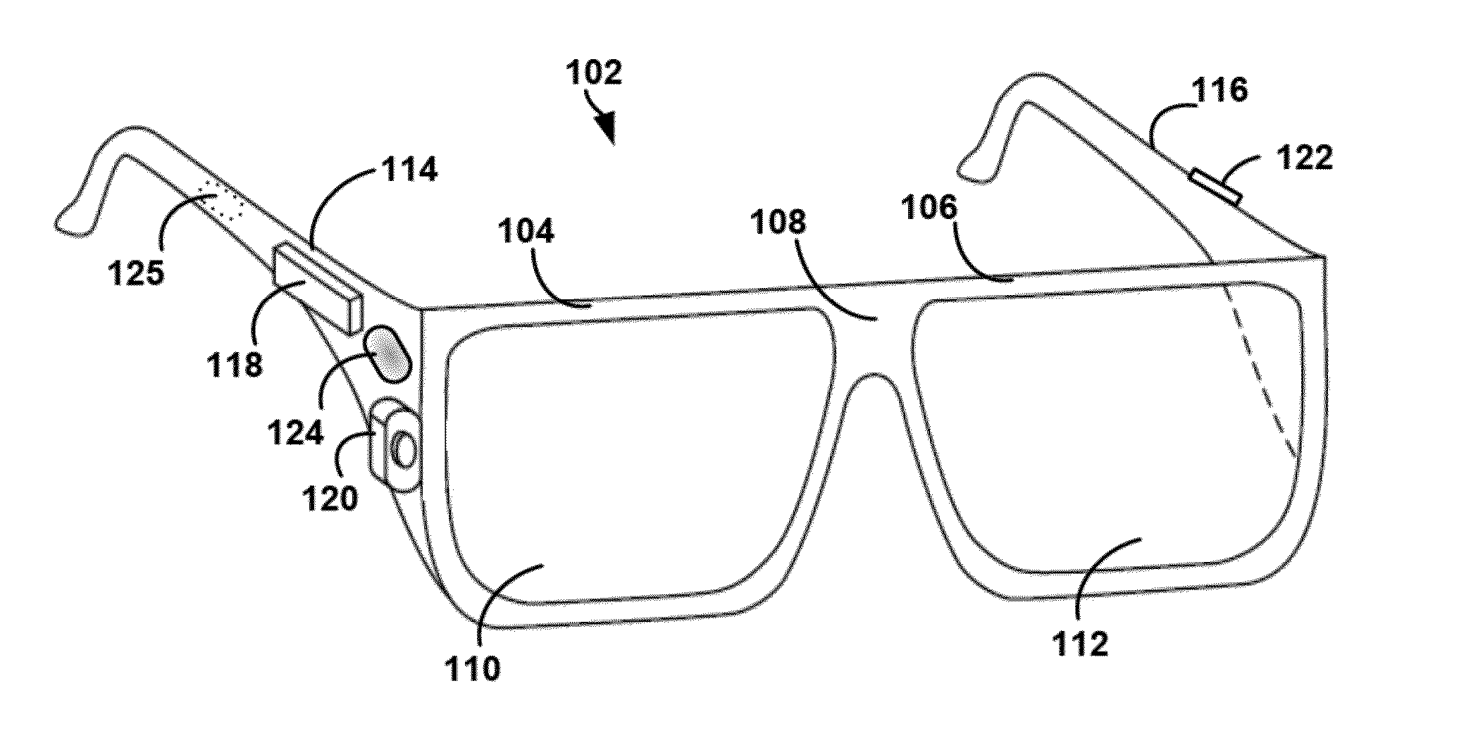
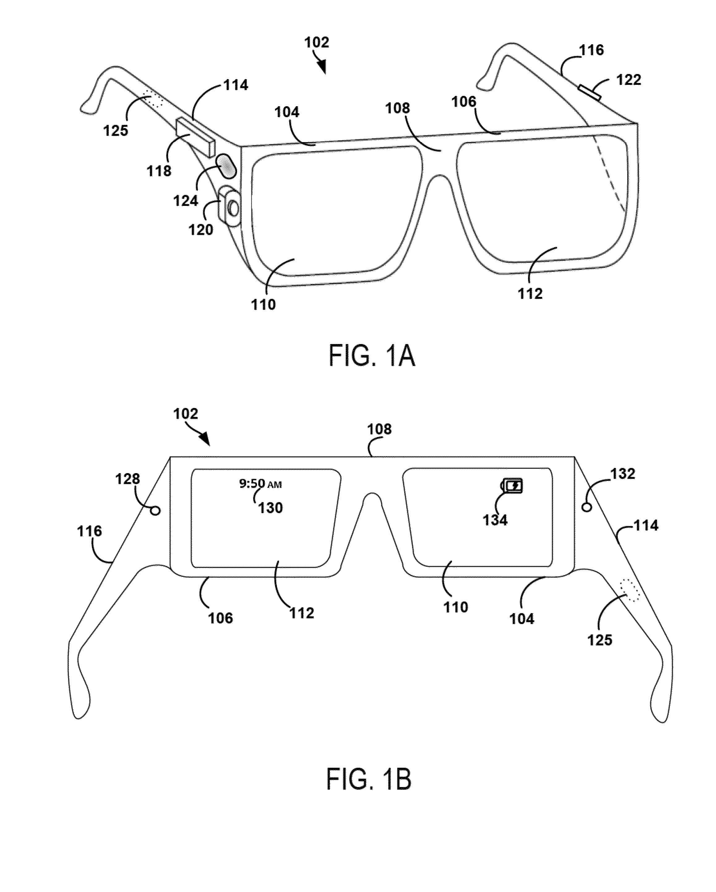
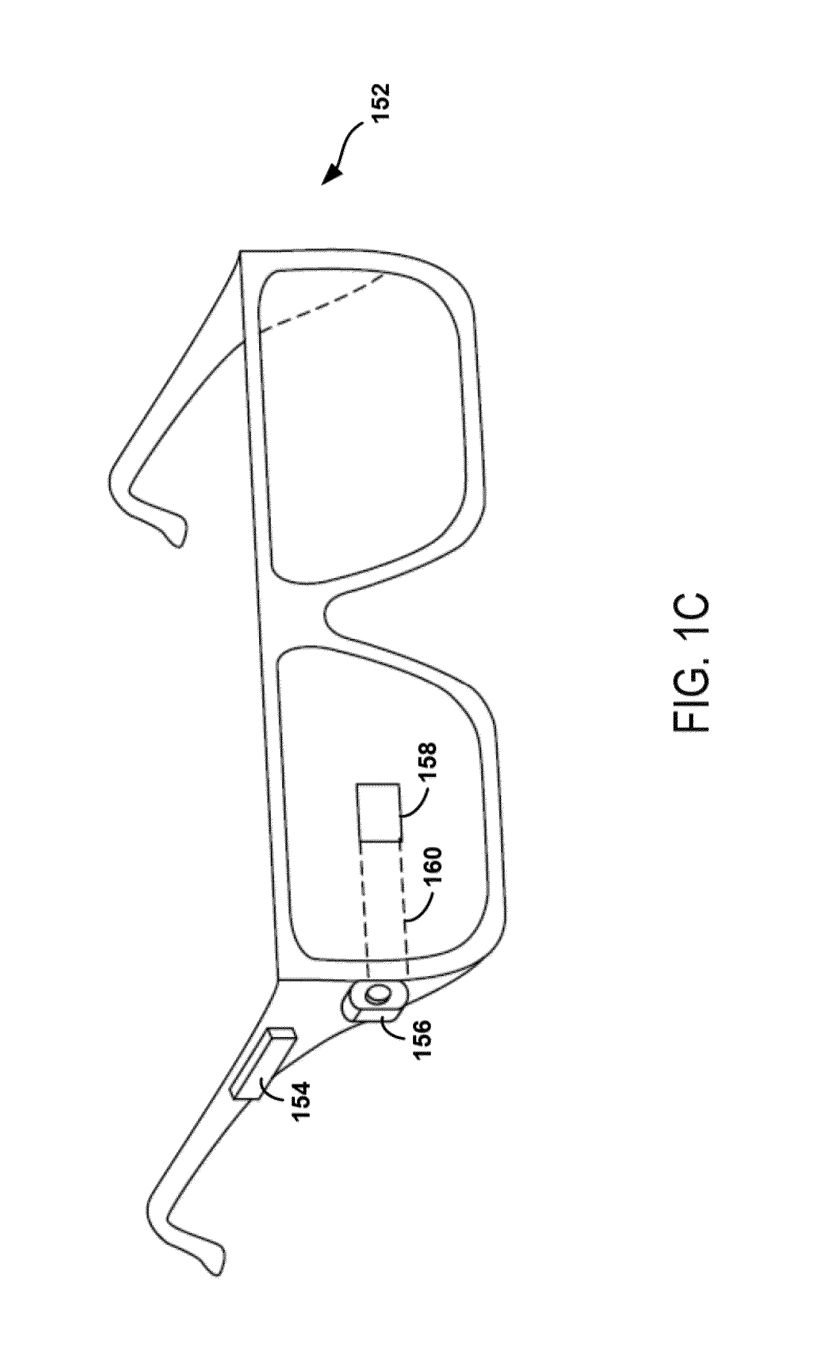
Modular frame construction for head mountable display
a module and display technology, applied in the direction of static indicating devices, instruments, cladding optical fibres, etc., can solve the problems of many limitations of devices, limited functionality, and limited fit and comfort of wearers of devices
- Summary
- Abstract
- Description
- Claims
- Application Information
AI Technical Summary
Benefits of technology
Problems solved by technology
Method used
Image

Examples
Embodiment Construction
[0020]Example methods and systems are described herein. It should be understood that the words “example” and “exemplary” are used herein to mean “serving as an example, instance, or illustration.” Any embodiment or feature described herein as being an “example” or “exemplary” is not necessarily to be construed as preferred or advantageous over other embodiments or features. In the following detailed description, reference is made to the accompanying figures, which form a part thereof. In the figures, similar symbols typically identify similar components, unless context dictates otherwise. Other embodiments may be utilized, and other changes may be made, without departing from the spirit or scope of the subject matter presented herein.
[0021]The example embodiments described herein are not meant to be limiting. It will be readily understood that the aspects of the present disclosure, as generally described herein, and illustrated in the figures, can be arranged, substituted, combined,...
PUM
 Abstract
Description
Claims
Application Information