Moving image encoding apparatus, control method thereof and computer program

a technology of moving image and encoding apparatus, applied in the direction of signal generator with optical-mechanical scanning, color television with bandwidth reduction, etc., can solve the problems of reducing encoding efficiency and insufficient reduction of block noise, so as to reduce block noise, reduce encoding efficiency, and reduce block noise.

Active Publication Date: 2014-08-07
CANON KK
View PDF18 Cites 12 Cited by
  • Summary
  • Abstract
  • Description
  • Claims
  • Application Information

AI Technical Summary

Benefits of technology

The present invention provides a technique to reduce block noise during motion compensation by performing deblocking filter processing with a filter intensity matching the degree of generated block noise. This technique effectively removes block noise and improves the efficiency of video encoding.

Problems solved by technology

However, if the deblocking filter processing is not performed with a filter intensity corresponding to the degree of block noise, a pattern of the image is blurred, or, on the contrary, the block noise cannot sufficiently be reduced.
Also, if block noise has not sufficiently been reduced when performing motion compensation by referring to an image having undergone the deblocking filter processing, block noise not existing in an unencoded original image exists in a predicted image after the motion compensation, and this decreases the encoding efficiency.

Method used


Image

  • Moving image encoding apparatus, control method thereof and computer program
  • Moving image encoding apparatus, control method thereof and computer program
  • Moving image encoding apparatus, control method thereof and computer program

Examples


first embodiment

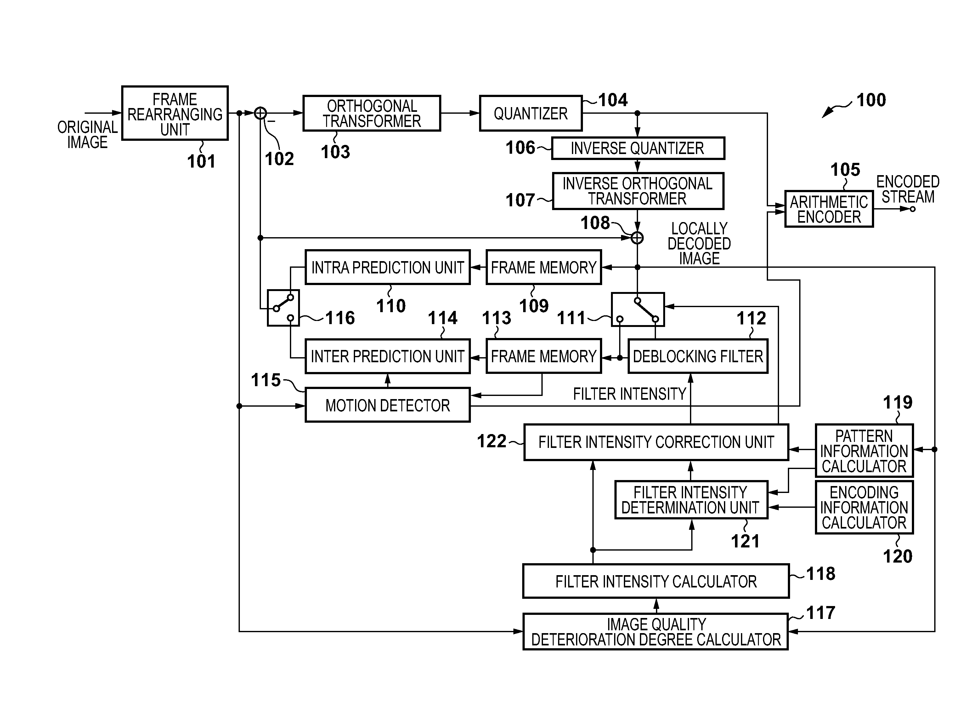
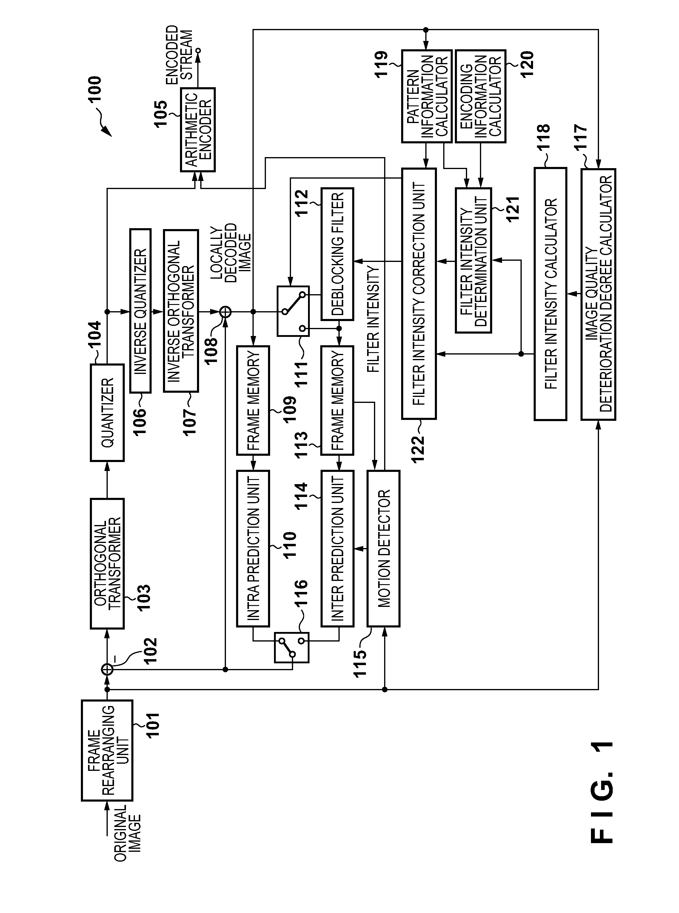
[0028]FIG. 1 is a block diagram showing an example of the arrangement of a moving image encoding apparatus according to an embodiment of the present invention. In a moving image encoding apparatus 100 according to this embodiment, a filter intensity calculated in accordance with the image quality deterioration degree of a locally decoded image with respect to an original image is corrected in accordance with encoding information and pattern information of the locally decoded image. The moving image encoding apparatus performs deblocking filter processing based on the corrected filter intensity. The example of the arrangement of the present invention will be explained below with reference to FIG. 1.

[0029]The moving image encoding apparatus 100 according to this embodiment includes a frame rearranging unit 101, subtracter 102, orthogonal transformer 103, quantizer 104, arithmetic encoder 105, inverse quantizer 106, inverse orthogonal transformer 107, adder 108, frame memories 109 and ...

second embodiment

[0096]FIG. 8 is a block diagram showing an example of a moving image encoding apparatus according to the second embodiment of the present invention. This encoding apparatus according to the second embodiment is a moving image encoding apparatus that performs deblocking filter processing based on the filter intensity calculated in accordance with the image quality deterioration degree and flatness of an original image and locally decoded image. The arrangement example of the present invention will be explained below with reference to FIG. 8.

[0097]The basic configuration of a moving image encoding apparatus 800 according to this embodiment is the same as that of the moving image encoding apparatus 100 of the first embodiment. That is, the moving image encoding apparatus 800 includes a frame rearranging unit 101, subtracter 102, orthogonal transformer 103, quantizer 104, arithmetic encoder 105, inverse quantizer 106, inverse orthogonal transformer 107, adder 108, frame memories 109 and...


PUM


Abstract

A filter intensity calculated in accordance with the image quality deterioration degree between an original image and locally decoded image is corrected in accordance with pattern information of the locally decoded image, and deblocking filter processing is performed by using the corrected filter intensity. The deblocking filter processing is performed by using a filter intensity which is calculated in accordance with the image quality deterioration degree between the original image and locally decoded image and the flatness of the original image or locally decoded image, and which increases as the image quality deterioration degree and flatness of an image increase.

Description

TECHNICAL FIELD[0001]The present invention relates to a moving image encoding apparatus, a control method thereof, and a computer program.BACKGROUND ART[0002]As a technique for efficiently encoding an image, a JPEG compression technique and encoding methods such as MPEG1 and MPEG2 using the motion prediction-motion compensation technique have been established. Manufacturers are developing and manufacturing image capturing apparatuses such as digital cameras and digital video cameras and DVD recorders capable of recording images on recording media by using these encoding methods.[0003]A digital moving image has an enormous data amount. To compress this enormous data amount, the compression ratio must be increased by performing coarse quantization when encoding each block. However, a quantization error occurring when the coarse quantization is performed produces a pixel value level difference in the block boundary. When the user watches the image, the image quality deteriorates becaus...

Claims


Application Information

Patent Timeline
Patent Type & Authority Applications(United States)
IPC IPC(8): H04N19/61H04N19/82
CPCH04N19/00896H04N19/00793H04N19/176H04N19/63H04N19/61H04N19/117H04N19/14H04N19/154H04N19/157H04N19/82H04N19/86H04N19/615
Inventor KOBAYASHI, SATORU
Owner CANON KK
Why Eureka
Try Eureka