
Round cutting insert with serrated topography

a cutting insert and topography technology, applied in the field of cutting inserts, can solve the problems of poor surface finish, premature insert wear and failure,

Active Publication Date: 2014-08-07
KENNAMETAL INC
View PDF15 Cites 6 Cited by
  • Summary
  • Abstract
  • Description
  • Claims
  • Application Information

AI Technical Summary

Benefits of technology

This patent is about a method to reduce chatter in a cutting tool with multiple cutting inserts. The method involves using a cutting insert with serrations on the top surface. The technical effect of this method is to improve the cutting performance of the tool.

Problems solved by technology

This regenerative chatter may cause premature insert wear and failure, as well as a poor quality surface finish.

Method used


Image

  • Round cutting insert with serrated topography
  • Round cutting insert with serrated topography
  • Round cutting insert with serrated topography

Examples


Embodiment Construction

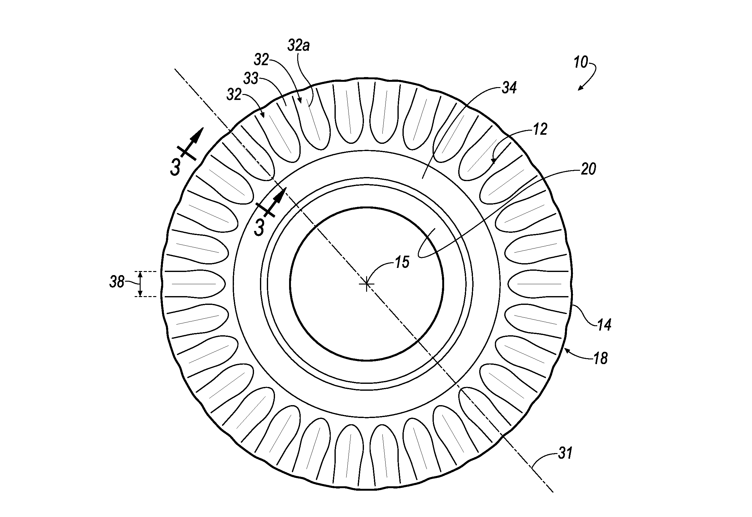
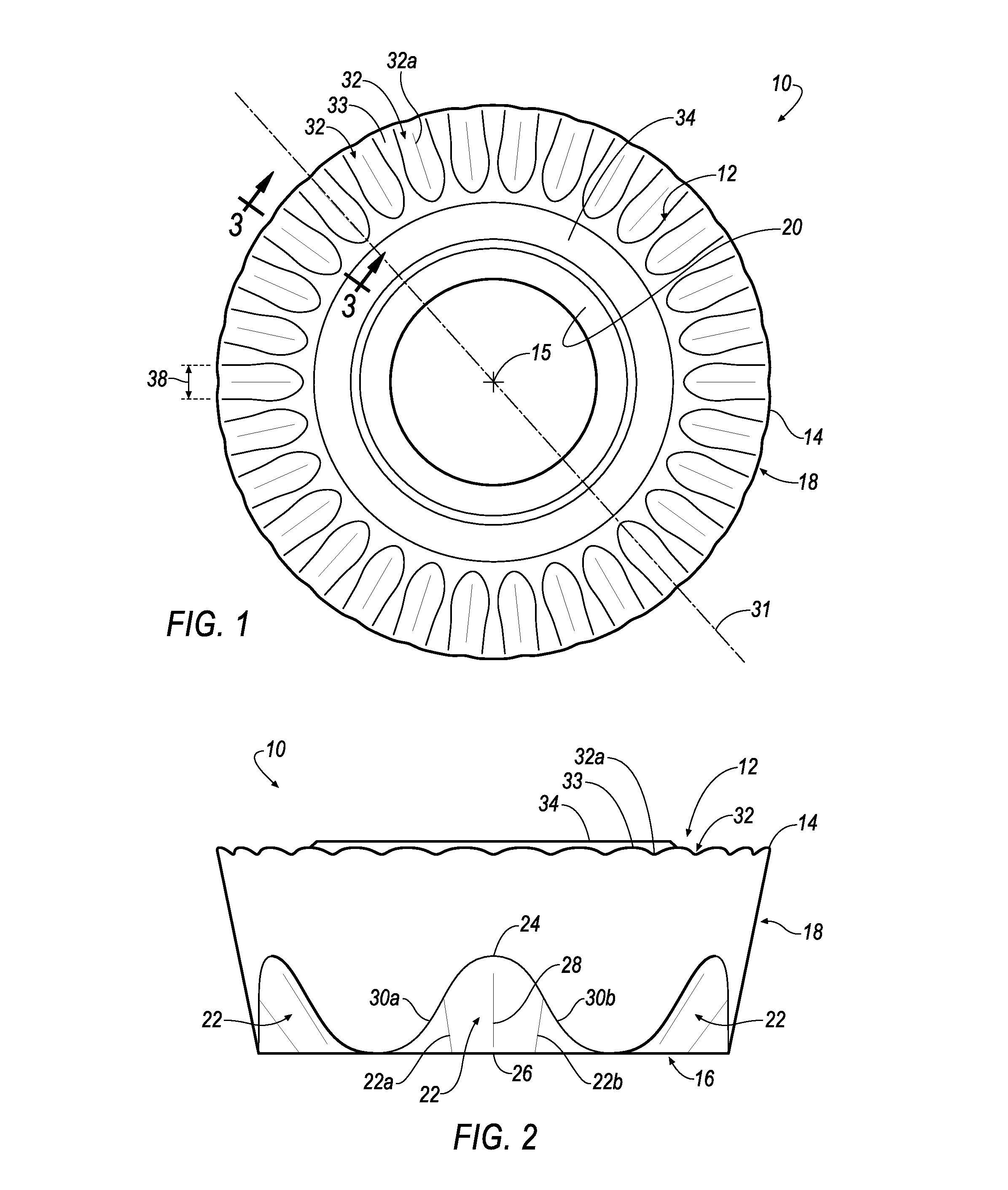
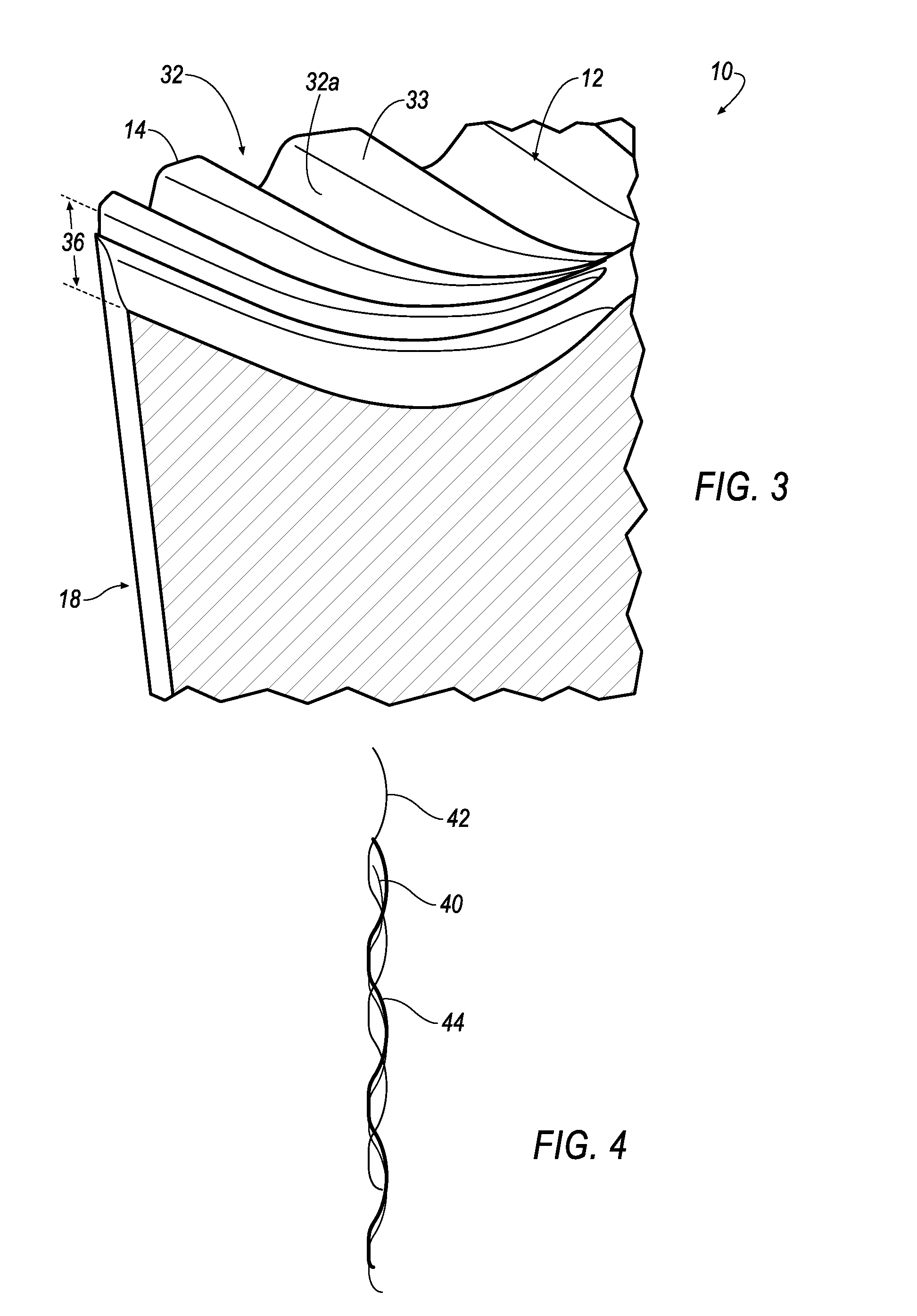
[0019]Referring now to FIGS. 1-3, a round cutting insert 10 is shown according to an embodiment of the invention. In general, the insert 10 has a top surface 12 that terminates in a circular cutting edge 14, a central axis 15, and a bottom surface 16 that engages a floor of a pocket when the insert 10 is mounted onto a cutter body of a cutting tool (not shown). The top surface 12 acts as a rake surface during a cutting operation. The insert 10 further has a frusto-conical sidewall 18 interconnecting the top surface 12 and bottom surface 16. A screw hole 20 is centrally disposed through the body of the insert 10 for receiving a threaded shank of a clamping screw (not shown).

[0020]A plurality of curved stop surfaces 22 are uniformly disposed around the frusto-conical sidewall 18 of the insert 10. Each of the curved stop surfaces 22 in the sidewall 18 of the insert 10 includes a pair of mirror-symmetrical oblique engagement portions 22a, 22b for forming an interference-type joint with ...


PUM

PropertyMeasurementUnit
depthaaaaaaaaaa
widthaaaaaaaaaa
pressureaaaaaaaaaa

Abstract

A cutting insert with a serrated topography includes a top surface terminating in a circular cutting edge, a bottom surface and a frusto-conical sidewall interconnecting the top surface and the bottom surface, and a plurality of serrations on the top surface uniformly disposed around the circular cutting edge and extending radially inward from the cutting edge in such a way that a bisector through each serration passes through a central axis of the cutting insert. The plurality of serrations are positioned in a cutting tool in such a way so as to reduce regenerative chatter during a cutting operation. A method of reducing generative chatter by positioning the cutting inserts in a particular fashion in a cutting tool is also disclosed.

Description

BACKGROUND OF THE INVENTION[0001]The invention relates in general to a cutting insert that may be detachably mounted on a tool holder for cutting a workpiece, and in particular to a cutting insert with a serrated topography that reduces or eliminates regenerative chatter during a cutting operation, while also reducing tool pressure.[0002]In conventional round cutting inserts, regenerative chatter is caused by repetition of the cutting edges that creates a frequency during a cutting operation. This regenerative chatter may cause premature insert wear and failure, as well as a poor quality surface finish.SUMMARY OF THE INVENTION[0003]The problem of regenerative chatter is solved by providing a cutting insert having a top surface with a plurality of serrations extending radially inward from the cutting edge.[0004]One purpose of the serrations of the invention is to break up the repetition of the cutting edges, thereby disrupting the frequency. This is accomplished by rotating the serra...

Claims


Application Information

Patent Timeline
Patent Type & Authority Applications(United States)
IPC IPC(8): B23C5/20B23C5/00
CPCB23C5/003B23C5/207B23C2200/045B23C2200/086B23C2200/125B23C2200/206B23C2250/16Y10T407/20Y10T29/49826Y10T407/1924Y10T407/245Y10T409/303752B23C5/202
Inventor HOFFER, BRAD DANIELLONG, II, THOMAS JERRY
Owner KENNAMETAL INC
Learn More