Supercharge Your Innovation With Domain-Expert AI Agents!

Bidirectional ratchet structure, bidirectional ratchet wrench and method for changing a direction thereof

a ratchet wrench and bi-directional technology, applied in the direction of wrenches, mechanical control devices, controlled parts, etc., can solve the problems of difficult operation, easy damage, and large volume of conventional bi-directional ratchet wrenches

Active Publication Date: 2014-08-14
KABO TOOL COMPANY
View PDF5 Cites 4 Cited by
  • Summary
  • Abstract
  • Description
  • Claims
  • Application Information

AI Technical Summary

Benefits of technology

The present patent describes a bidirectional ratchet structure that allows for easy changing of the direction of a ratchet wrench. The structure includes a base, two pawl elements, two reset elements, a direction controller, and a driving element. The direction controller is pivotally and coaxially disposed at the base and surrounds the first and second pawl elements. The driving element is pivotally and coaxially disposed at the base and surrounds the first and second pawl elements. The driving element includes an inner tooth portion that engages with the first and second pawl elements. The technical effect of this structure is that it allows for easy and quick adjustment of the ratchet wrench's direction of rotation.

Problems solved by technology

However, the conventional bidirectional ratchet wrench has a lot of disadvantages.
For example, the structure of the bidirectional ratchet wrench is not stable due to a bidirectional ratchet structure.
Furthermore, the conventional bidirectional ratchet structure is usually controlled by a small switching button, which is unreliable, easily damaged, and difficultly operated.
As a result, a conventional bidirectional ratchet wrench has a certain degree of operation inconvenience.

Method used


Image

  • Bidirectional ratchet structure, bidirectional ratchet wrench and method for changing a direction thereof
  • Bidirectional ratchet structure, bidirectional ratchet wrench and method for changing a direction thereof
  • Bidirectional ratchet structure, bidirectional ratchet wrench and method for changing a direction thereof

Examples


Embodiment Construction

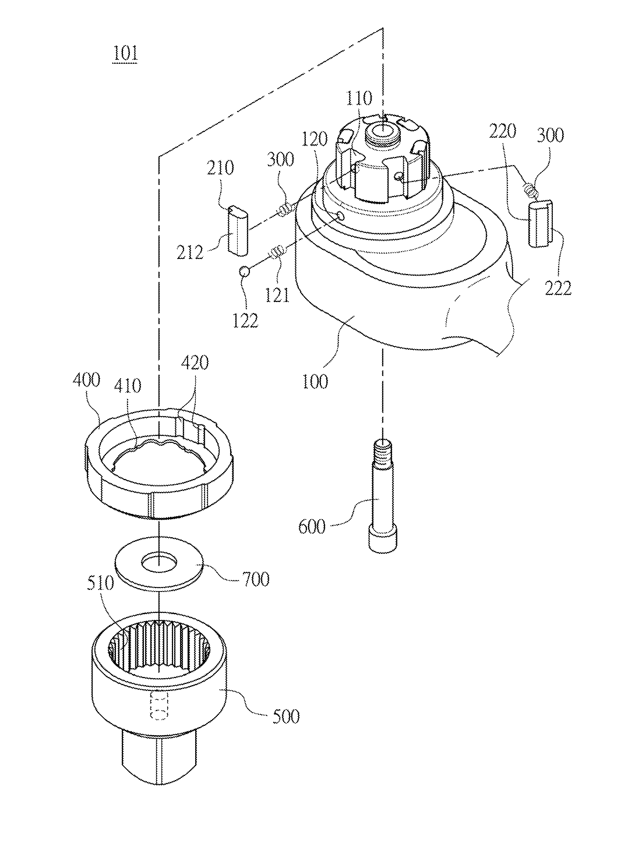
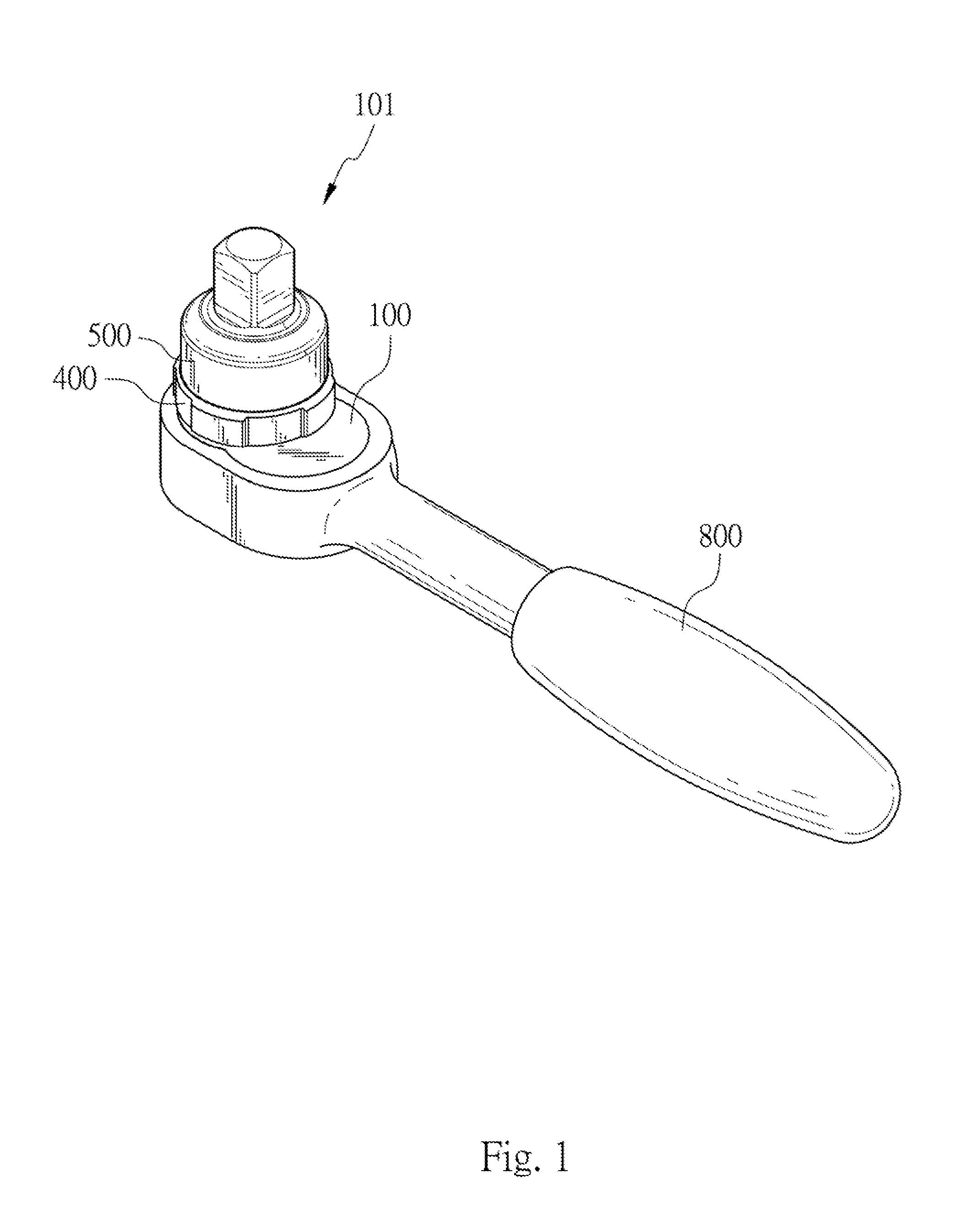
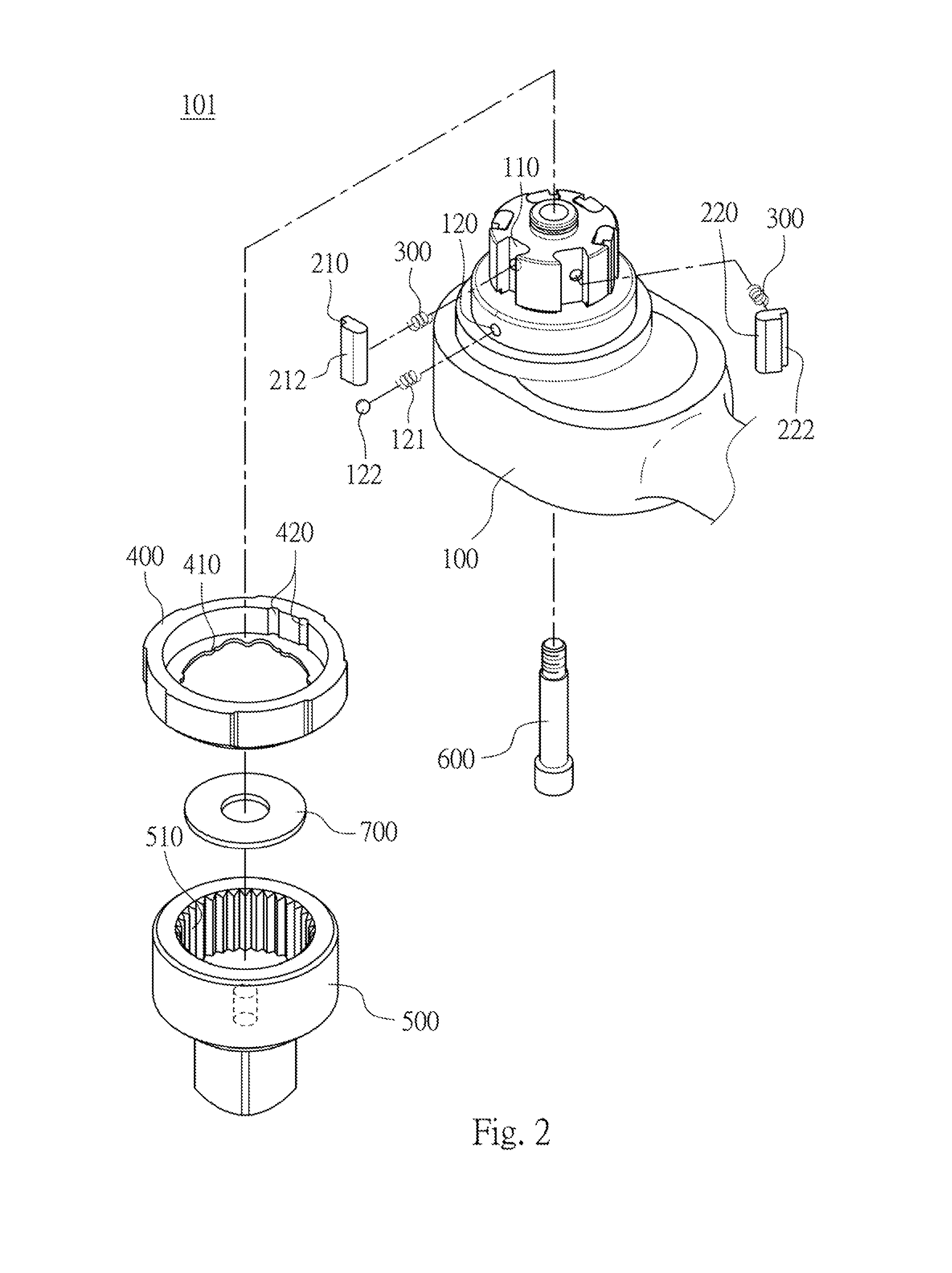
[0016]FIG. 1 is a three dimensional view of a bidirectional ratchet wrench according to one embodiment of the present disclosure. FIG. 2 is an exploded view of a bidirectional ratchet structure 101 as illustrated in FIG. 1. FIG. 3 is a cross-sectional view of the bidirectional ratchet structure 101 as illustrated in FIG. 1. FIG. 4 is a schematic view showing a direction controller 400 pressing three first pawl elements 210 toward a base 100 as illustrated in FIG. 2. In FIG. 1 the bidirectional ratchet wrench includes a bidirectional ratchet structure 101 and a handle 800. The bidirectional ratchet structure 101 is connected with the handle 800. The handle 800 is for being held by a user. The bidirectional ratchet structure 101 is fixedly connected with an end of the handle 800, and the handle 800 is but not limited to be formed in an H shape. In other embodiment, the bidirectional ratchet structure 101 can be connected with a middle of the handle 800 or pivotally connected with the ...


PUM


Abstract

A bidirectional ratchet structure includes a base, a first pawl element, a second pawl element, two reset elements, a direction controller and a driving element. The first pawl element, the second pawl element, the direction controller and the driving element are pivotally disposed at the base. The first pawl element includes a first engaging portion. The second pawl element includes a second engaging portion. The first engaging portion and the second engaging portion are pushed to protrude from the base alternatively. The two reset elements are for pushing the first engaging portion and the second engaging portion to protrude from the base respectively. The first pawl element and the second pawl element are surrounded by the direction controller and the driving element. The direction controller is for pressing the first pawl element or the second pawl element toward the base.

Description

RELATED APPLICATIONS[0001]This application claims priority to Taiwan Application Serial Number 102105433, filed Feb. 8, 2013, which is herein incorporated by reference.BACKGROUND[0002]1. Technical Field[0003]The present disclosure relates to a ratchet structure, a ratchet wrench and a method for changing a direction thereof. More particularly, the present disclosure relates to a bidirectional ratchet structure, a bidirectional ratchet wrench and a method for changing a direction thereof.[0004]2. Description of Related Art[0005]A ratchet wrench is a kind of widely used hand tool. The ratchet wrench allows the user to tighten or loosen a screw by using a back-and-forth motion without removing the ratchet wrench from the screw. Therefore, the ratchet wrench simplifies the tightening and loosening process and thus enhances the work efficiency apparently. Furthermore, the ratchet wrench can be used in a confined space. As a result, the ratchet wrench has become an indispensable product n...

Claims


Application Information

Patent Timeline
IPC IPC(8): B25B13/46
CPCB25B13/465Y10T74/214
Inventor HSIEH, CHIH-CHING
Owner KABO TOOL COMPANY
Features
  • R&D
  • Intellectual Property
  • Life Sciences
  • Materials
  • Tech Scout
  • Unparalleled Data Quality
  • Higher Quality Content
  • 60% Fewer Hallucinations
Learn More