Retainer systems for ground engaging tools

Active Publication Date: 2014-09-18
CATERPILLAR INC
View PDF20 Cites 20 Cited by
  • Summary
  • Abstract
  • Description
  • Claims
  • Application Information

AI Technical Summary

Problems solved by technology

These implements can be subjected to extreme wear from the abrasion and impacts experienced during the ea

Method used


Image

  • Retainer systems for ground engaging tools
  • Retainer systems for ground engaging tools
  • Retainer systems for ground engaging tools

Examples


Embodiment Construction

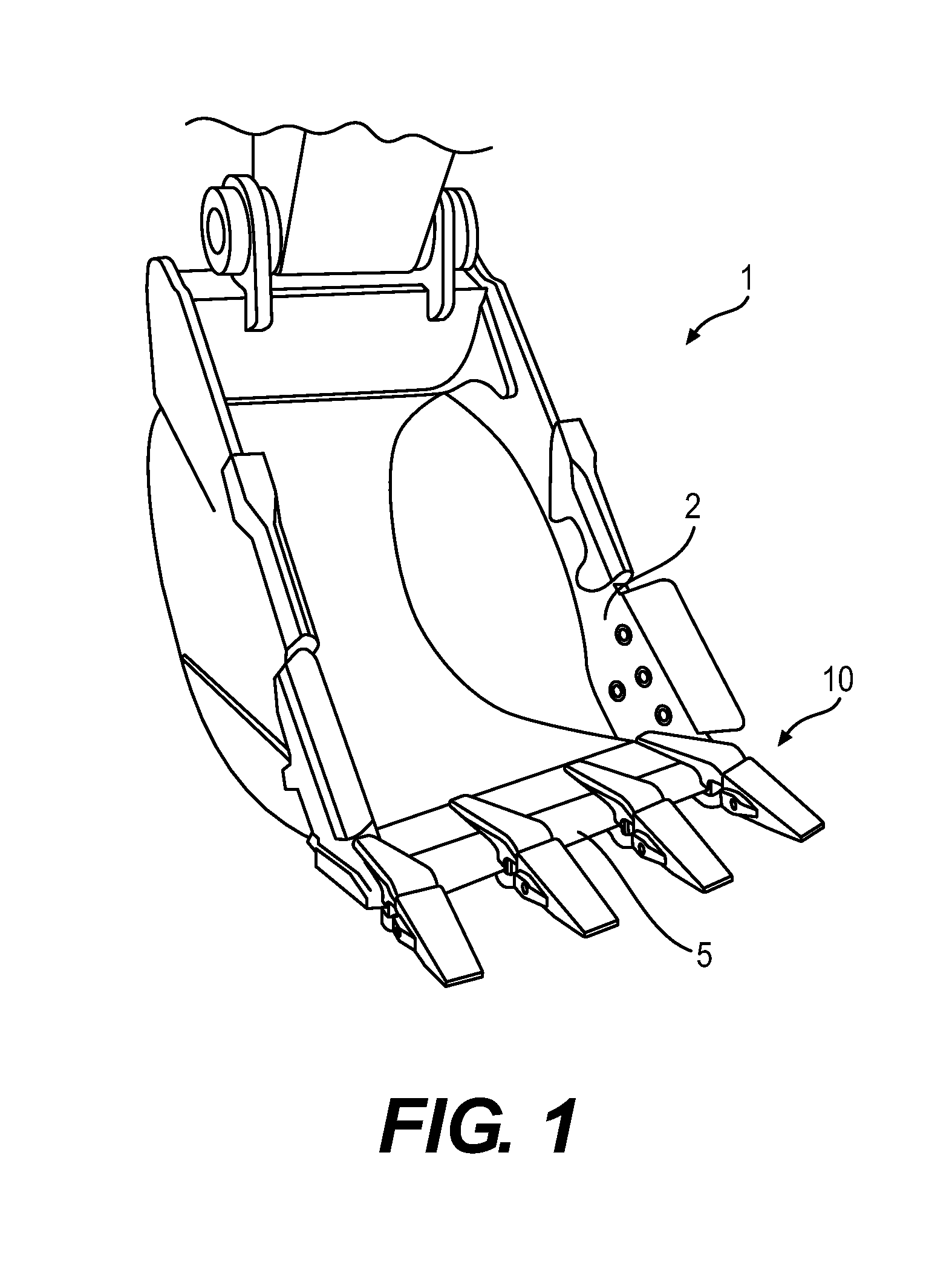
[0033]FIG. 1 illustrates an excavator bucket assembly 1 as an exemplary implement of an earth-working machine. Excavator bucket assembly 1 includes a bucket 2 used for excavating work material in a known manner. Bucket 2 may include a variety of ground engaging tools. For example, bucket 2 may include a plurality of tooth assemblies 10, as ground engaging tools, attached to a base edge 5 of bucket 2. Tooth assemblies 10 may be secured to bucket 2 employing retainer systems according to the present disclosure. While various embodiments of the present disclosure will be described in connection with a particular ground engaging tool (e.g., tooth assembly 10), it should be understood that the present disclosure may be applied to, or used in connection with, any other type of ground engaging tools or components. Further, it should be understood that one or more features described in connection with one embodiment can be implemented in any of the other disclosed embodiments unless otherwi...


PUM


Abstract

Disclosed are various exemplary embodiments of a retainer bushing for use with a lock of a ground engaging tool. The retainer bushing may include a skirt extending around a retainer axis, where the skirt may include an outer surface configured to mate with a lock cavity of the ground engaging tool and an inner surface configured to rotatably receive an outer surface of the lock. The retainer bushing may also include a detent projection extending radially inward from the inner surface and configured to engage a detent recess of the lock to resist rotation of the lock. The skirt and the detent projection may be integrally constructed of a thermoplastic material comprising polyoxymethylene.

Description

TECHNICAL FIELD[0001]The present disclosure relates generally to ground engaging tools and, more particularly, to retainer systems for removably attaching the ground engaging tools to various earth-working machines.BACKGROUND[0002]Earth-working machines, such as, for example, excavators, wheel loaders, hydraulic mining shovels, cable shovels, bucket wheels, bulldozers, and draglines, are generally used for digging or ripping into the earth or rock and / or moving loosened work material from one place to another at a worksite. These earth-working machines include various earth-working implements, such as a bucket or a blade, for excavating or moving the work material. These implements can be subjected to extreme wear from the abrasion and impacts experienced during the earth-working applications.[0003]To protect these implements against wear, and thereby prolong the useful life of the implements, various ground engaging tools, such as teeth, edge protectors, and other wear members, can...

Claims


Application Information

Patent Timeline
IPC IPC(8): E02F9/28
CPCE02F9/2833E02F9/2841F16B7/22F16B21/02
Inventor LAHOOD, JAMES ROBERT
Owner CATERPILLAR INC
Why Eureka
Try Eureka