Check patentability & draft patents in minutes with Patsnap Eureka AI!

Low power, space combined, phased array radar

a phased array radar and low power technology, applied in the field of low power, space combined, phased array radar, can solve the problems of low aerodynamic drag, low range resolution, high cost of current radar applications, etc., and achieve the effect of simple fixed beam

Active Publication Date: 2014-10-02
HONEYWELL INT INC
View PDF10 Cites 7 Cited by
  • Summary
  • Abstract
  • Description
  • Claims
  • Application Information

AI Technical Summary

Benefits of technology

The system achieves efficient beam steering and multiple beam formation with reduced weight and aerodynamic drag, improving range resolution and coverage while minimizing RF losses and complexity, suitable for UAVs and other applications requiring low-weight, low-drag radar systems.

Problems solved by technology

Current radar applications, in particular marine radar, are expensive, have significant weight, and have less than optimal range resolution.
Also, these applications are ineffective at covering exceptionally large scanned volumes, such as on unmanned aerial vehicles (UAVs) where hemispheres of coverage are required with very low weight (a few pounds to a few tens of pounds) and very low aerodynamic drag.
Previous design efforts have shown that active phased arrays (every element has its awn transmit, receive, amplitude, and phase control) are expensive, complex, and heavy.
Also, passive phased arrays with a central high-powered. transmitter and passive low-pass phase shifters are less complex and have many advantages, but they are inefficient with RF transmission losses on both transmit and receive sides, despite all efforts to control losses in the power distribution network.

Method used


Image

  • Low power, space combined, phased array radar
  • Low power, space combined, phased array radar
  • Low power, space combined, phased array radar

Examples


Embodiment Construction

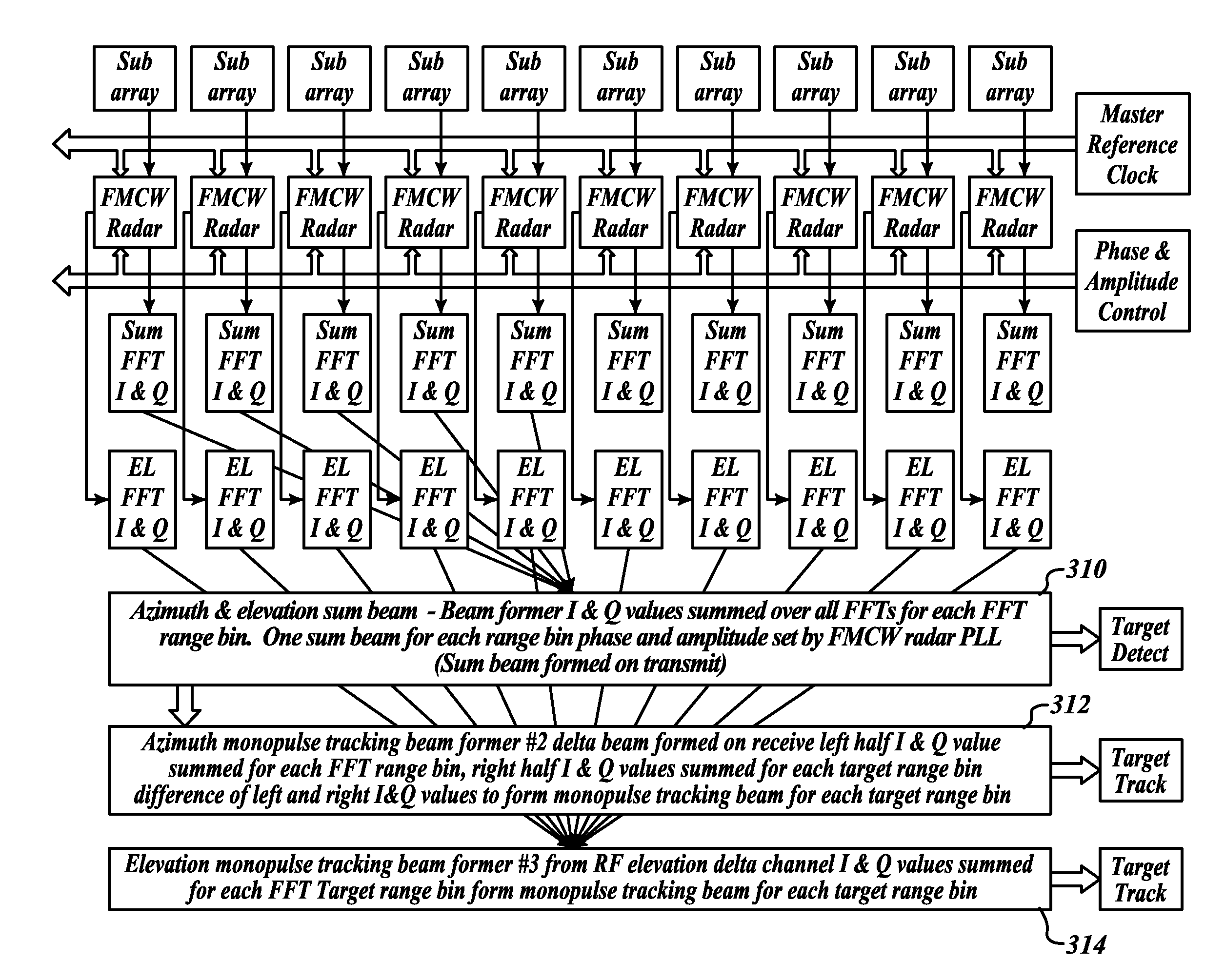
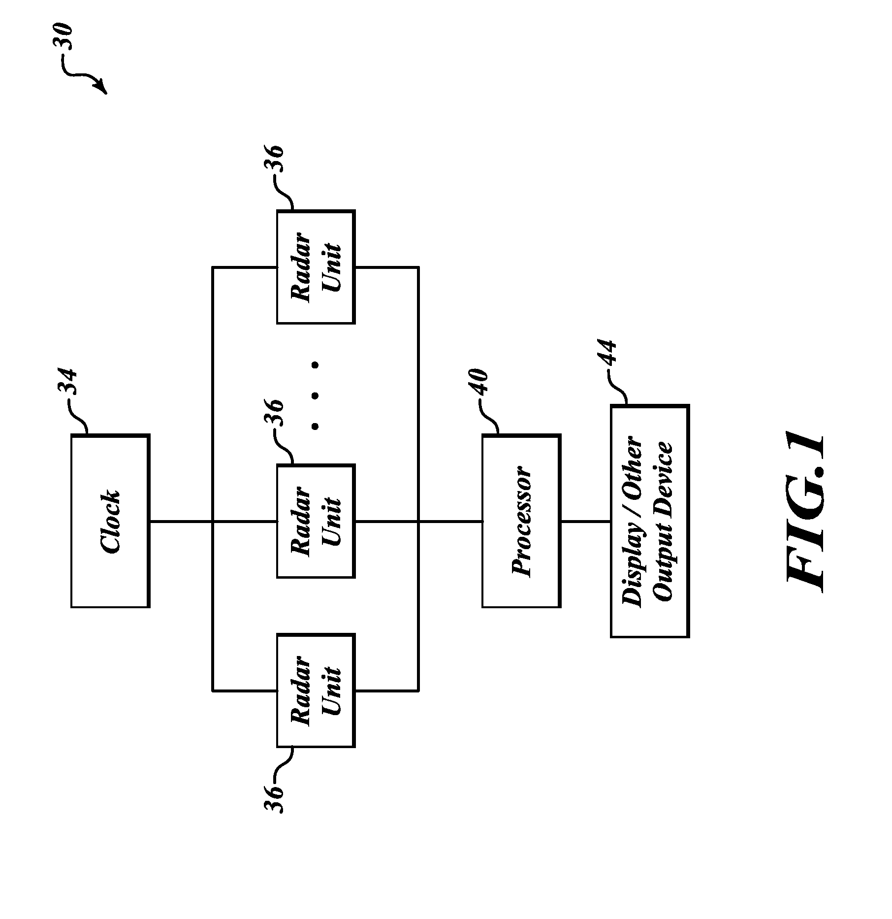
[0016]FIG. 1 illustrates an exemplary radar system 30 that includes multiple radar units 36 (mini frequency-modulated / continuous-wave (FM / CW) radars or Linear FM Pulse Compression). Each of the radar units 36 is phase locked to a master timing oscillator (a clock 34). Each radar unit 36 can have its transmitted modulation phase or FFT Processed receive signal adjusted (I&Q FFT Outputs multiplied by complex weight) such that a passive phase shifter function in a common phased array is performed. Also, output power from each of the radar units 36 is adjustable to allow amplitude taper on an array of antennas, to adjust beam steering, or both.

[0017]The system 30 includes a processor 40 that is connected to each of the radar units 36 and a display or other type of output device 44 that is in signal communication with the processor 40. Adjusting the relative phase of digital phase lock loops within each of the radar units 36 permits electronic beam steering, electronic beam farming, or b...


PUM


Abstract

A radar system including a plurality of mini radars may be conformable to a structure that it is attached or built into. A radar system includes a clock, a plurality of frequency modulated / continuous wave (FM / CW) radar units in signal communication with the clock and a processor in signal communication with the plurality of FM / CW radar units. Each of the plurality of FM / CW radar units includes a row of antenna elements.

Description

[0001]This application is a continuation of application Ser. No. 13 / 011,771 by Vacanti et al., tiled Jan. 21, 2011 and entitled, “LOW POWER, SPACE COMBINED, PHASED ARRAY RADAR,” which claims the benefit of U.S. Provisional Application 61 / 306,271 by Vacanti et al., filed Feb. 19, 2010 and entitled, “LOW POWER, SPACE COMBINED, PHASED ARRAY RADAR”, the entire content of each of which are hereby incorporated by reference.BACKGROUND OF THE INVENTION[0002]Current radar applications, in particular marine radar, are expensive, have significant weight, and have less than optimal range resolution. Some applications require a simple mechanically scanned array and some applications require electronic beam steering for high-speed review of a scanned volume. Also, these applications are ineffective at covering exceptionally large scanned volumes, such as on unmanned aerial vehicles (UAVs) where hemispheres of coverage are required with very low weight (a few pounds to a few tens of pounds) and ve...

Claims


Application Information

Patent Timeline
Patent Type & Authority Applications(United States)
IPC IPC(8): G01S7/03G01S13/44H01Q3/34
CPCG01S7/03G01S2013/0254G01S13/44H01Q3/34
Inventor VACANTI, DAVID C.POS, MARC
Owner HONEYWELL INT INC
Features
  • R&D
  • Intellectual Property
  • Life Sciences
  • Materials
  • Tech Scout
  • Unparalleled Data Quality
  • Higher Quality Content
  • 60% Fewer Hallucinations
Learn More