
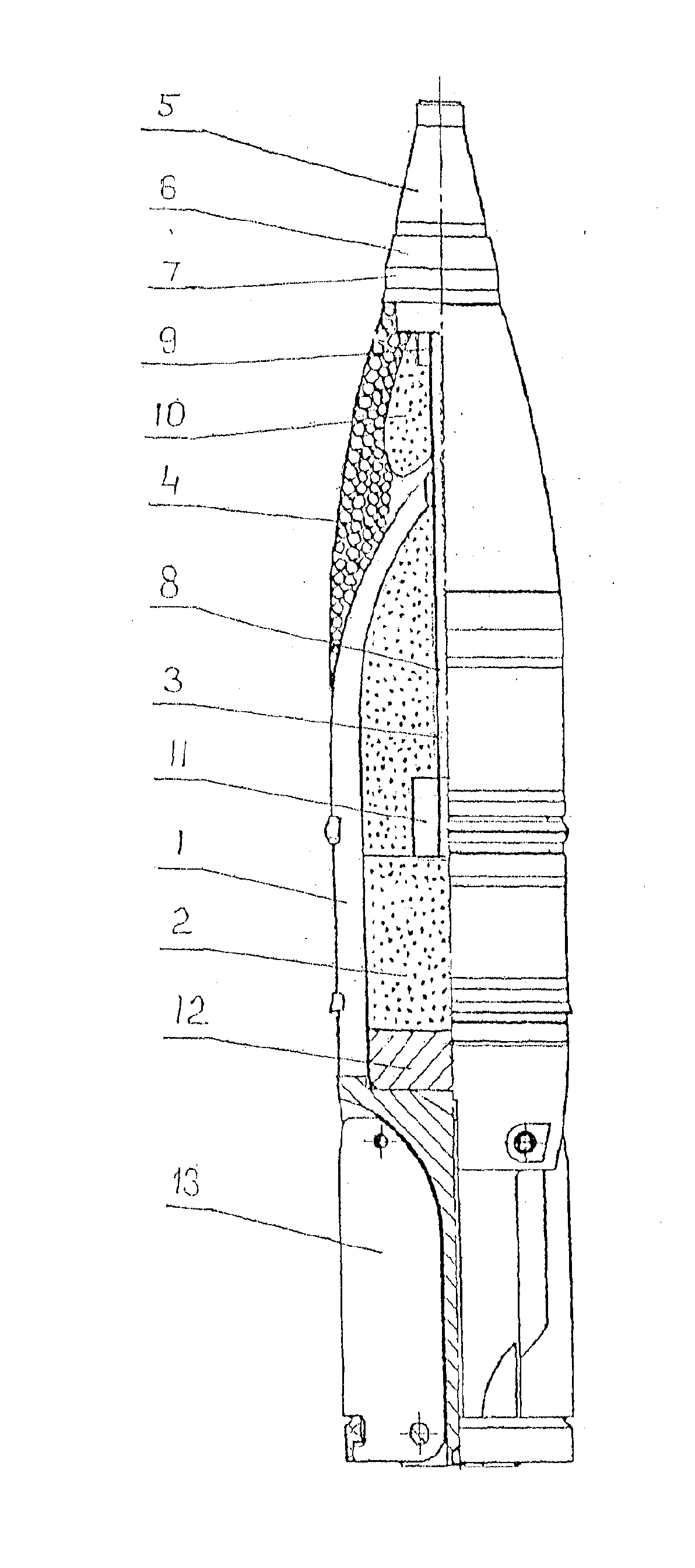
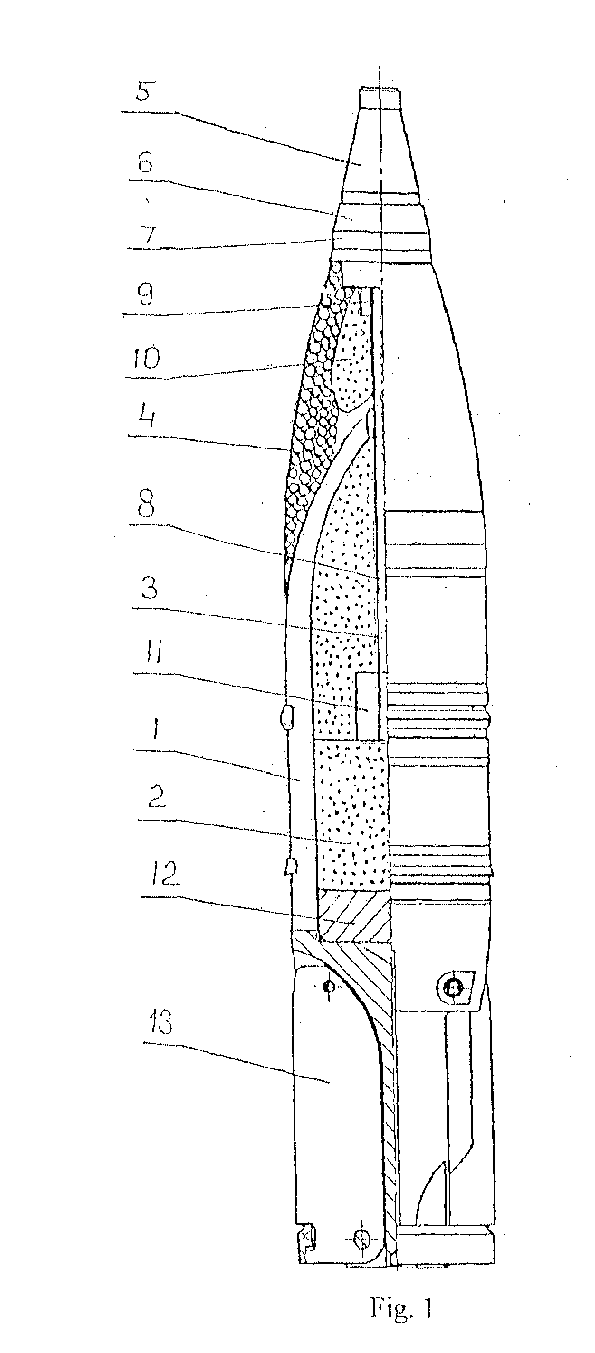
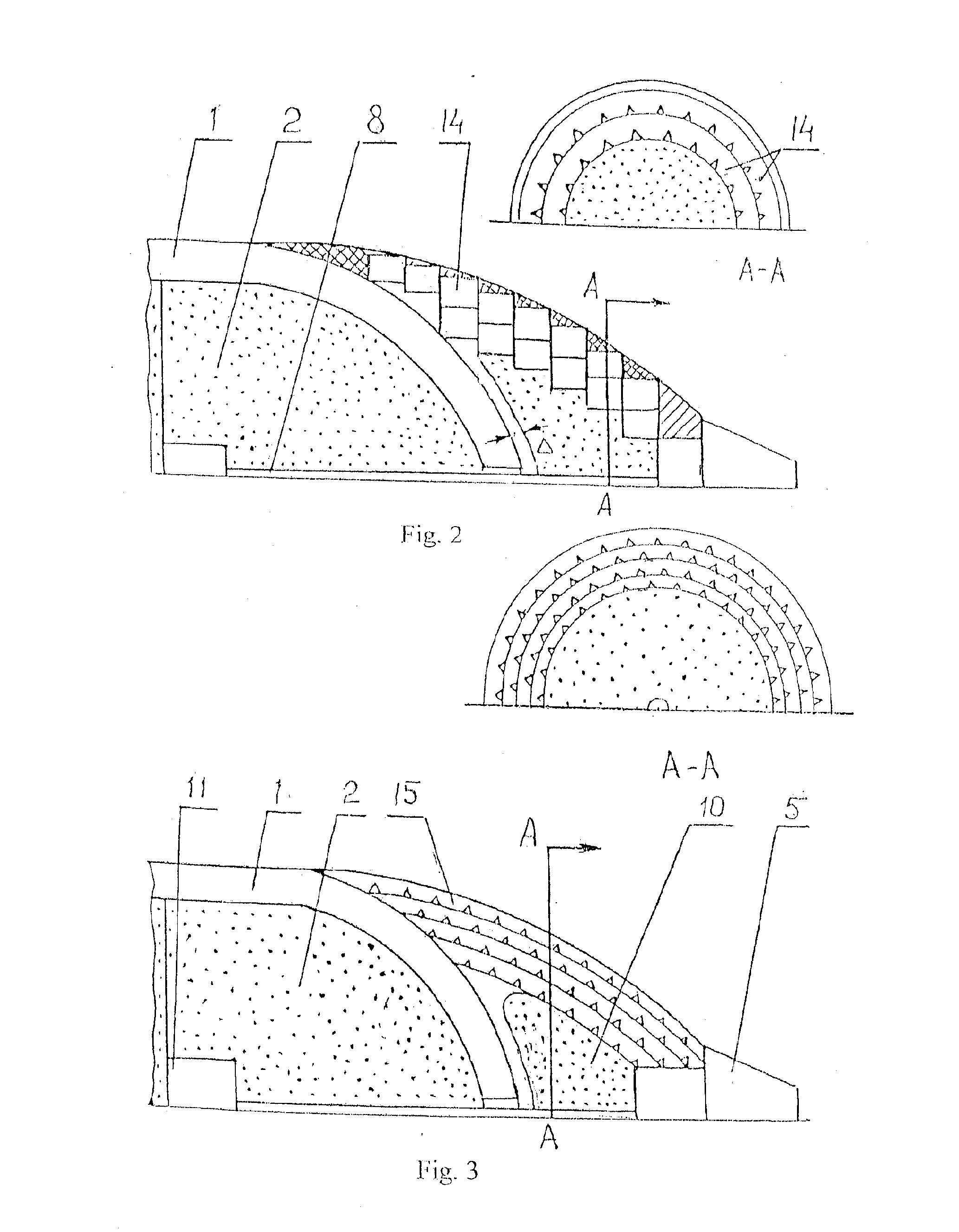
Fragmentation-beam tank projectile

a technology of fragmentation beam and projectile, which is applied in the direction of ammunition projectiles, projectiles, weapons, etc., can solve the problems of reducing the strength of the projectile casing head section, incompleting the destruction of the fragmentation unit, and large diameter of the axial channel in the charg

Active Publication Date: 2014-10-09
FEDERAL STATE BUDGETARY EDUCATIONAL INSTION OF HIGHER PROFESSIONAL EDUCATION BAUMAN MOSCOW STATE TECHN UNIV +1
View PDF3 Cites 9 Cited by
  • Summary
  • Abstract
  • Description
  • Claims
  • Application Information

AI Technical Summary

Benefits of technology

The invention is a better way to destroy a target. It involves a long gun with a detonator in it that can be activated at different times to optimize the destruction of the target. The detonator is connected to a fuse, which in turn controls when the detonator can be activated. The detonators are also safe and designed to explode in a controlled manner. This invention makes the process more effective than previous methods.

Problems solved by technology

The main disadvantage of said known projectile is the fixed axial field shape of the fabricated destructive elements which does ensure reliable destruction of tank threatening targets of different classes (single, grouped including groups of different configurations, ground, air etc.).
Another disadvantage is the possibility of incomplete destruction of the fragmentation unit following explosive charge detonation in the projectile.
Yet another disadvantage is the large diameter of the axial channel in the charge necessitated by the installation of a detonator with a safety device and reducing the strength of the projectile casing head section.

Method used


Image

  • Fragmentation-beam tank projectile
  • Fragmentation-beam tank projectile
  • Fragmentation-beam tank projectile

Examples


Embodiment Construction

Projectile Functioning

[0022]The projectile is programmable and provides the following functionality depending on the settings:[0023]trajectory explosion (destruction) during target approach (at a prediction point);[0024]ground impact explosion with preset instantaneous (fragmentation) action;[0025]ground impact explosion with preset fragmentation / high-explosive action (low deceleration);[0026]ground impact explosion with preset penetration / high-explosive action (high deceleration).

[0027]Before the shot the tank fire control system determines target type, distance, azimuth relative to the tank, target configuration for grouped targets and the required fuse settings.

[0028]For trajectory destruction the tank's fire control electronics calculates the flight to destruction time, the destruction height, the optimum projectile and fragmentation unit charge explosion time interval and the gun firing elevation.

[0029]Fuse settings are contact or contactless entered into the fuse through the s...


PUM


Abstract

This invention relates to fragmentation-beam ammunition capable of simultaneous axial and circular field destruction.The objects of this invention are providing a variable configuration axial field of the fabricated destructive elements for the reliable destruction of different types of tank threatening targets and providing for the complete destruction of the fragmentation unit following explosive charge detonation in the projectile.The technical solution according to this invention, the projectile comprises an elongated explosive charge with a detonator in the form of a rotation body with a curvilinear generatrix located coaxially with the fragmentation unit wherein said detonator is electrically connected with the fuse and said fuse comprises a device (an adapter booster) for varying the time interval between the activation of both detonators depending on the setting, said detonators comprising safety devices.

Description

FIELD OF THE INVENTION[0001]This invention relates to fragmentation beam ammunition capable of simultaneous axial and circular fields of injury.BACKGROUND OF THE INVENTION[0002]Known is a fragmentation-beam projectile comprising a casing with a monolithic head section having an axial channel, an explosive charge with a detonator located in the middle section of the charge, a head section trajectory-contact fuse electrically connected to the detonator, a fragmentation unit located between the casing and the fuse and externally enveloping the projectile head section, and a screw-in bottom with stabilizing fins (RU 2327948, publ. Jun. 27, 2008).[0003]Said composite fragmentation unit comprises fabricated destructive elements in a binder matrix.[0004]The main disadvantage of said known projectile is the fixed axial field shape of the fabricated destructive elements which does ensure reliable destruction of tank threatening targets of different classes (single, grouped including groups o...

Claims


Application Information

Patent Timeline
IPC IPC(8): F42B12/28F42B10/02F42B12/32F42B12/22
CPCF42B12/28F42B12/32F42B10/02F42B12/22F42B10/14F42B12/24
Inventor ODINTSOV, VLADIMIR ALEKSEEVICH
Owner FEDERAL STATE BUDGETARY EDUCATIONAL INSTION OF HIGHER PROFESSIONAL EDUCATION BAUMAN MOSCOW STATE TECHN UNIV
Learn More