Bicycle pedal

a bicycle pedal and pedal body technology, applied in the field of bicycle pedals, can solve the problems of accidental disengagement of difficulty in step-in operation for some riders, and difficulty in removing the cleat from the bicycle pedal, and achieve the effect of improving the ability to clear mud

Active Publication Date: 2014-10-23
SHIMANO INC
View PDF16 Cites 3 Cited by
  • Summary
  • Abstract
  • Description
  • Claims
  • Application Information

AI Technical Summary

Benefits of technology

[0007]With such a conventional bicycle pedal, the pivot pin and the spring of the second cleat securing member (rotatably coupled to the main pedal body) are located relatively close to a pedal axle. With such an arrangement, mud tends to stick to around the center portion of a bicycle pedal (i.e. around a pedal axle) during riding in muddy conditions. Thus, in the conventional structure, mud tends to stick to the spring, which is relatively close to the pedal axle. Mud does not always come off easily from the bicycle pedal due to the shape and location of the spring relatively close to the pedal axle. Accordingly, one object of this disclosure is to provide a bicycle pedal with improved mud clearing ability.
[0008]Also, with such a conventional bicycle pedal, if the biasing force of the spring is increased in order to prevent accidental disengagement of the cleat from the bicycle pedal during riding (i.e., to hold the cleat more securely during extreme riding), the step-in operation may become difficult for some riders due to increased force needed for step-in. On the other hand, if the biasing force of the spring is decreased in order to obtain an easier step-in operation, accidental disengagement of the cleat from the bicycle pedal may occur during riding such as during extreme off-road (mountain bike) riding. In other words, it can be difficult to obtain an ideal spring force during riding and for a relatively easy step-in operation for some riders. Accordingly, another object of this disclosure is to provide a bicycle pedal, which facilitates a relatively easy step-in operation yet reduces the possibility accidental disengagement of the cleat from the bicycle pedal during riding.

Problems solved by technology

Thus, in the conventional structure, mud tends to stick to the spring, which is relatively close to the pedal axle.
Mud does not always come off easily from the bicycle pedal due to the shape and location of the spring relatively close to the pedal axle.
Also, with such a conventional bicycle pedal, if the biasing force of the spring is increased in order to prevent accidental disengagement of the cleat from the bicycle pedal during riding (i.e., to hold the cleat more securely during extreme riding), the step-in operation may become difficult for some riders due to increased force needed for step-in.
On the other hand, if the biasing force of the spring is decreased in order to obtain an easier step-in operation, accidental disengagement of the cleat from the bicycle pedal may occur during riding such as during extreme off-road (mountain bike) riding.
In other words, it can be difficult to obtain an ideal spring force during riding and for a relatively easy step-in operation for some riders.

Method used


Image

  • Bicycle pedal
  • Bicycle pedal
  • Bicycle pedal

Examples


Embodiment Construction

[0042]Selected embodiments will now be explained with reference to the drawings. It will be apparent to those skilled in the art from this disclosure that the following descriptions of the embodiments are provided for illustration only and not for the purpose of limiting the invention as defined by the appended claims and their equivalents.

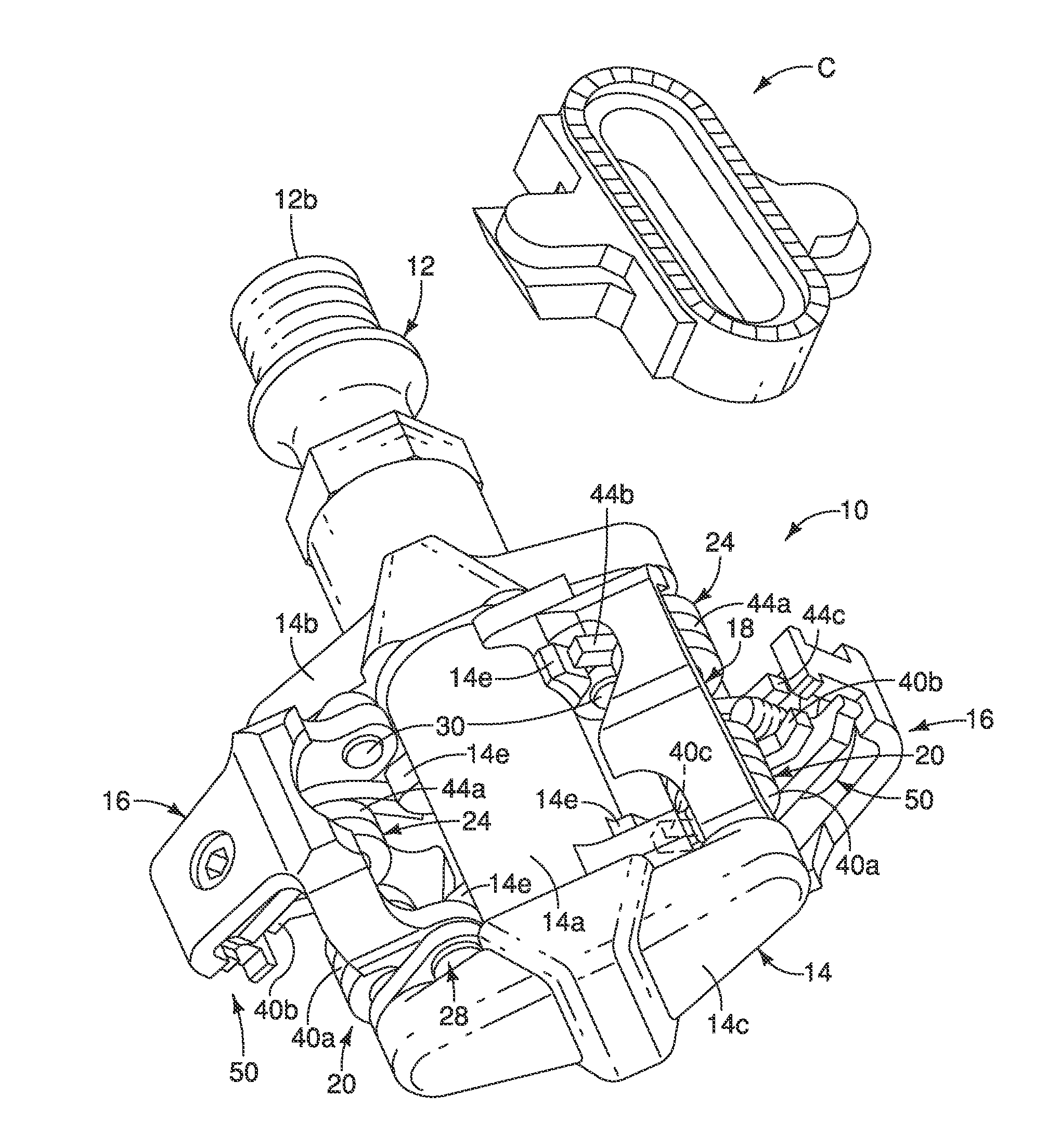
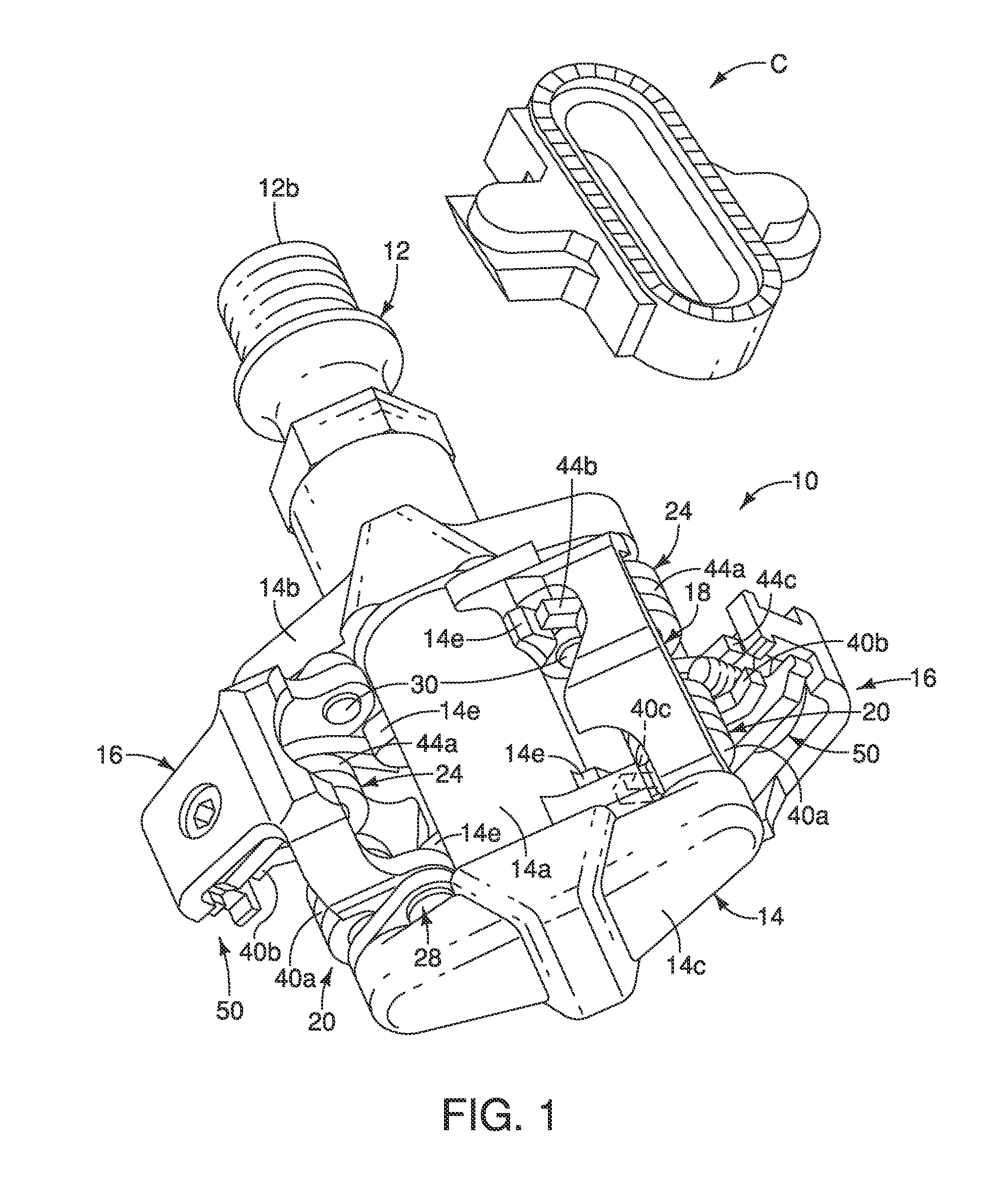
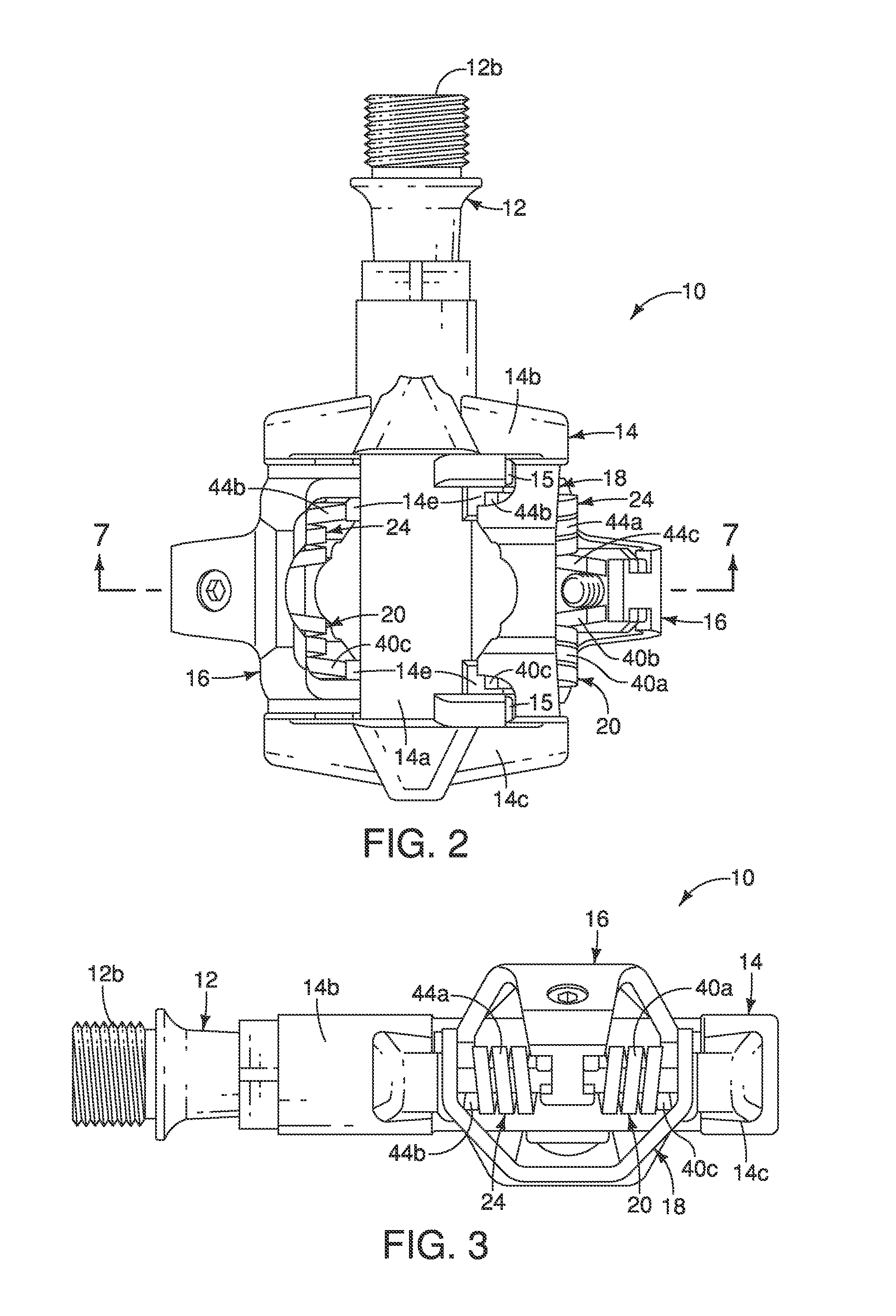
[0043]Referring initially to FIG. 1, a bicycle pedal 10 is illustrated in accordance with a first embodiment. In the illustrated embodiment, the bicycle pedal 10 is a two-sided (e.g. mountain bicycle style) bicycle pedal that basically includes a pedal axle 12, a main pedal body 14, a pair of first cleat securing members 16, a pair of a sub members 18, and a pair of first biasing members 20. One of the first cleat securing members 16, one of the sub members 18 and one of the first biasing members 20 is mounted at each longitudinal end of the main pedal body 14. The first biasing members 20 bias the first cleat securing members 16 toward clamping p...


PUM


Abstract

A bicycle pedal includes a pedal axle, a rotatable main pedal body, a first cleat securing member pivotally coupled about a first pivot axis between first and second positions, a sub member pivotally coupled to move about a second pivot axis, and at least a first biasing member disposed on the second pivot axis. The second pivot axis is farther from the pedal axle than the first pivot axis. The first biasing member is operatively disposed between the main pedal body and the first cleat securing member to bias the first cleat securing member toward the first position. The first cleat securing member and the sub member rotate together about the second pivot axis until the sub member abuts against the main pedal body, and the first cleat securing member subsequently rotates toward the second position about the first pivot axis independently from the sub member during a step-in operation.

Description

BACKGROUND[0001]1. Field of the Invention[0002]This invention generally relates to a bicycle pedal. More specifically, the present invention relates to bicycle pedal that can be releasably attached to a cleat of a cycling shoe.[0003]2. Background Information[0004]A conventional clipless pedal that can connect to a cleat attached to a shoe is a known example of a bicycle pedal that can connect to a cycling shoe (e.g., European Patent Application Publication No. 1,219,532). When a clipless type bicycle pedal is used, the crank can be rotated during a down stroke as well by pulling upward. As a result, the crank can be rotated more efficiently.[0005]A conventional clipless bicycle pedal includes a pedal axle that can be attached to a crank of a bicycle, a main pedal body rotatably supported on the pedal axle, and a coupling mechanism. The coupling mechanism is fixed to two opposite faces of the pedal main pedal body and has a first cleat securing member configured to couple with a fron...

Claims


Application Information

Patent Timeline
Patent Type & Authority Applications(United States)
IPC IPC(8): B62M3/08
CPCB62M3/086Y10T74/217
Inventor INOUE, AKIRA
Owner SHIMANO INC
Why Eureka
Try Eureka