

Convex supporting device
a support device and ostomy technology, applied in the field of ostomy base plates, can solve the problems of not being able to find an optimal balance range for users, and achieve the effect of maintaining the necessary peristomal pressure, reducing the risk of pressure ulcers, and reducing the risk of ulcers
- Summary
- Abstract
- Description
- Claims
- Application Information
AI Technical Summary
Benefits of technology
Problems solved by technology
Method used
Image

Examples
example 1
Details of Example 1
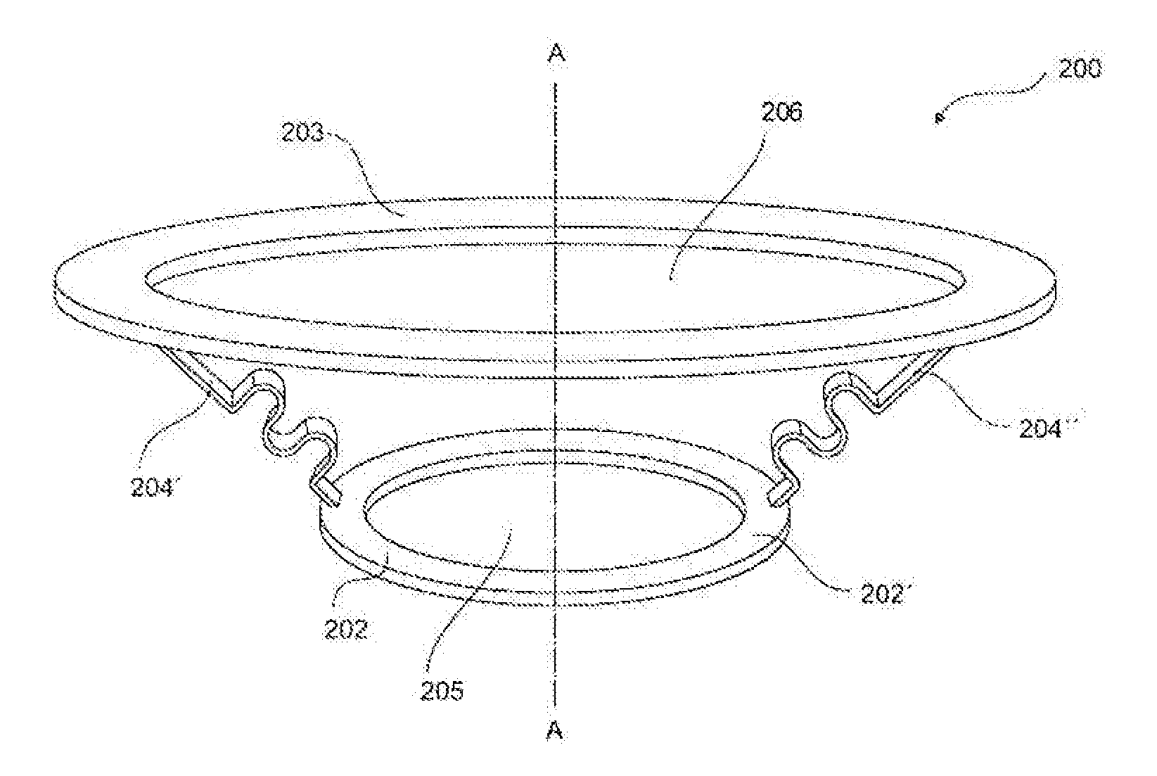
[0117]A supporting device 200 for supporting a skin area is shown in FIG. 9. The supporting device has a proximal annular ring 202. The proximal annular ring 202 is connected to a distal annular ring 203 via spring element 204′ and 204″.
[0118]The proximal annular ring is formed as a circular ring and has a proximal through-going hole 205 which has a size suitable for enclosing a desired skin area, for example a stoma or a wound site.
[0119]The distal annular ring is also formed as a circular ring and has a distal through-going hole 206. The distal annular ring has a larger circumference than the proximal annular ring.
[0120]This allows for easy access to the proximal through-going hole 205 through the distal through-going hole 206.
[0121]The proximal annular ring 202 and the distal annular ring 203 are displaced along the longitudinal axis A-A which extends through the centres of both the annular rings.
[0122]The proximal annular ring 202 and the distal annular ring ...
example 2
Details of Example 2
[0143]FIGS. 15-18 show a supporting member 300 having the advantages as described herein.
[0144]The supporting member 300 is in the form of an annular ring which is defined by an outer edge 303 and an inner edge 304. The inner edge 304 also defines a through-going hole 305 through which a stoma can be received when the supporting member is incorporated into a base plate for use in an ostomy appliance.
[0145]The through-going hole defines an axis C-C, corresponding to the central axis of the inner edge. The inner edge 304 is eccentrically placed in respect to the outer edge 303, thereby dividing the supporting member 300 into two areas, i.e. a first area 306 where the radial distance from the inner edge to the outer edge is larger than in a second area 307.
[0146]Three stiffening elements 308, 309, 310 extend radially from the inner edge 304 towards the outer edge 303 in the first area 306. The stiffening elements are formed as grooves in the supporting member 300 ha...
example 3
Details of Example 3
[0155]FIG. 19 shows a supporting element 400, and FIGS. 20 and 21 show a base plate 401 formed of an adhesive wafer 407 and the supporting element 400. The adhesive wafer 407 has an adhesive 402 disposed on a backing layer 403 so that the adhesive wafer has an adhesive proximal surface and a non-adhesive distal surface.
[0156]The supporting element is attached to the non-adhesive distal surface by e.g. gluing or welding. The adhesive wafer 407 is formed with a first through-going hole 406 and the supporting element has a second through-going hole 408. The adhesive wafer and the supporting element are aligned so that the first and second through-going holes are coaxially aligned along a central axis C-C. This allows for a stoma to be received by the base plate 401.
[0157]The supporting element is formed by an inner annular ring 409, which provides support and stability to the skin area encircled by the ring which corresponds to the second through-going hole 408.
[015...
PUM
 Abstract
Description
Claims
Application Information