Sampler and sampling method

a sampling method and sampler technology, applied in the field of samplers, can solve the problems of molten material taken up into the sample chamber, slow cooling, and difficult cooling, and achieve the effect of rapid cooling and easy cooling

Active Publication Date: 2014-10-30
HERAEUS ELECTRO NITE INT NV
View PDF15 Cites 61 Cited by
  • Summary
  • Abstract
  • Description
  • Claims
  • Application Information

AI Technical Summary

Benefits of technology

[0012]It is therefore an object of the invention to devise a way in which the disadvantages described above can be reduced or overcome. Specifically, a way is to be devised for rapid and easy cooling of a sample taken up into a sample chamber, such that the solid sample arising during the cooling process can be removed from the molten material only a short time after taking up the molten material. Moreover, the sample should be prevented from reacting, for example with ambient air, by the cooling process being rapid.

Problems solved by technology

One disadvantage of the prior art as known to date is that the molten material taken up into the sample chamber, which later forms the sample, cools down only very slowly in the sample chamber.

Method used


Image

  • Sampler and sampling method
  • Sampler and sampling method
  • Sampler and sampling method

Examples


Embodiment Construction

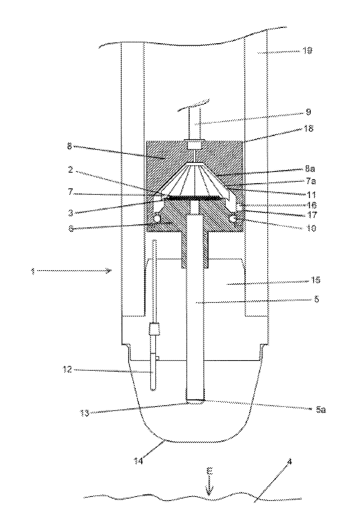
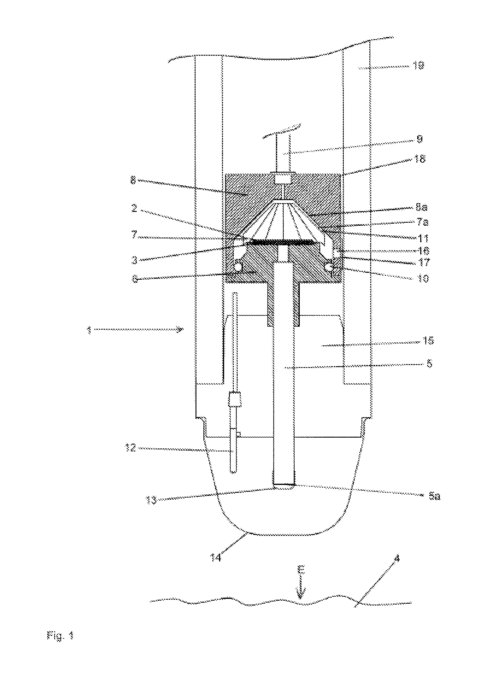
[0089]FIG. 1 shows a sampler 1 that had been immersed into a liquid and hot bath of molten material for the purpose of sampling.

[0090]The sampler 1 comprises a sample chamber 2. A sample 3 is shown in exemplary manner in the sample chamber 2 shown in FIG. 1 and has been formed from a molten material, from molten steel 4 in the present exemplary embodiment. The molten steel 4 has a temperature of above 600° C. and is shown as a detail in exemplary manner in FIG. 1.

[0091]The sampler 1 further comprises a filling tube 5 that comprises a filling opening 5a and a through-going hole. The filling tube 5 consists of quartz glass in the present exemplary embodiment. At the end facing the sampler, the filling tube 5 merges into the sample chamber 2 and is connected to the sample chamber 2.

[0092]According to FIG. 1, the sampler 1 comprises three cooling bodies in the present exemplary embodiment, namely a lower cooling body 6, an upper cooling body 8, and an inner cooling body 7. According to ...


PUM

PropertyMeasurementUnit
melting temperatureaaaaaaaaaa
temperatureaaaaaaaaaa
diameteraaaaaaaaaa

Abstract

A sampler has a sample chamber for a sample forming from a molten material, at least one lower cooling body, at least one upper cooling body, at least one inner cooling body, and at least one filling part. The sample chamber is surrounded jointly at least by the lower cooling body and the inner cooling body, such that at least the sample chamber can be cooled by at least the lower and inner cooling bodies. The filling part merges into the sample chamber by a filling opening. Between a region of the outer surface of the inner cooling body and a region of the outer surface of the upper cooling body opposite the outer surface of the inner cooling body, the sampler has at least one gap for conducting at least one gas. The volume of the respective cooling bodies is larger than the volume of the gap.

Description

BACKGROUND OF THE INVENTION[0001]The invention relates to a sampler having a sample chamber for a sample forming from a molten material, preferably for a sample forming from a molten metal, in particular from molten crude iron or molten steel. The sampler comprises at least one lower cooling body, at least one upper cooling body, at least one inner cooling body, and at least one filling part, preferably one filling tube, wherein the sample chamber is surrounded jointly at least by the lower cooling body and the inner cooling body, preferably is surrounded directly jointly, such that at least the sample chamber can be cooled by at least the lower and inner cooling bodies, wherein the filling part connected to the sample chamber merges into the sample chamber by a filling opening, and wherein the cooling bodies each comprise an outer surface.[0002]Moreover, the invention relates to a method for sampling from a molten material having a melting temperature of more than 600° C., in parti...

Claims


Application Information

Patent Timeline
Patent Type & Authority Applications(United States)
IPC IPC(8): G01N1/12
CPCG01N1/125G01N33/205Y10S73/09B01L3/502715B01L2200/0684B01L2300/0681B01L2300/0832B01L2400/0463G01N1/1409B01L3/502
Inventor CAPPA, GUIDOBROEKMANS, GERRIT
Owner HERAEUS ELECTRO NITE INT NV
Why Eureka
Try Eureka