Process for manufacturing a bearing

a manufacturing process and bearing technology, applied in the direction of shaft assembly, rotary machine parts, mechanical equipment, etc., can solve the problems of micro cracks forming in the hard facing material, and achieve the effects of more radial space, more loading capacity, and strong and ruggedness

Inactive Publication Date: 2011-06-09
ASHMIN L C
View PDF17 Cites 2 Cited by
  • Summary
  • Abstract
  • Description
  • Claims
  • Application Information

AI Technical Summary

Benefits of technology

[0014]An advantage of the present invention includes use of an outer diameter fusion process which eliminates the need for separate radial bearing systems and components. Another advantage is that the radial bearing product of the present invention is stronger and more rugged than prior art bearings. Yet another advantage is that the coating of the present invention will endure the severe temperature and shock loads imposed on down hole tools employed in boring holes in subterranean formations.
[0015]Another advantage of the present invention is that no radial bearing components are needed other than the housing and mandrel, which are an integral part of a radial bearing. Thus, a more robust mandrel and housing can be used since more radial space is available within the housing. Accordingly, more loading capacity and better reliability are experienced with the radial bearing of the present disclosure.
[0016]Yet another advantage is the rapid cooling of the hard facing material in one embodiment which allows for good particle distribution. Also, the rapid cooling process allows, in one preferred embodiment, for the formation of micro cracks in the hard facing material.
[0017]A feature of the present invention is that the materials used are applied to the outer diameter of a core sleeve. Another feature is that the outer diameter of the core sleeve, with the materials of the present invention applied thereto, can be machined with conventional tools. Still yet another feature is that the core sleeve, after application of the various materials, can be machined from the inner diameter using known milling and grinding tools. A feature of the present invention is that the starting tubular sleeve may be of sufficient length that it is possible for the operator, after the application of the various layers and machining of the outer and inner diameter, to cut the bearings into several predetermined lengths so that a plurality of bearings are produced, which will result in cost savings and lessen the manufacturing time.
[0018]In another embodiment, a process for manufacturing a radial bearing for use in a down hole mud motor may include providing a tubular sleeve having a first inner surface and a first outer surface and fusing a hard facing material on the first outer surface of the tubular sleeve to form a second outer surface of the tubular sleeve. The process may include fusing a material layer on the second outer surface of the tubular sleeve to form a third outer surface of the tubular sleeve. The process may include controlled cooling the hard facing material from a process temperature of about 3500 degrees Fahrenheit to a temperature of about 500 degrees Fahrenheit in a material specific time period in the range of two to five minutes. The third outer surface of the tubular sleeve may be machined so that a portion of the material layer is removed, and the first inner surface of the tubular sleeve may be machined to form a second inner surface of the tubular sleeve composed of the hard facing material. The process may also include cutting the length of the tubular sleeve, machining the third outer surface of the tubular sleeve, machining the second inner surface of the tubular sleeve in order to form a radial bearing. The radial bearing may be placed into a housing and a mandrel may be inserted into the radial bearing. The mandrel may have an outer surface with a hard coating so that the hard coating of the mandrel abuts the radial bearing.
[0019]The process may further include slowly cooling the material layer after the material specific time period by providing an insulation layer around the third outer surface of the tubular sleeve. The material layer may cooled to a temperature of 250 degrees Fahrenheit with the insulation layer around the third outer surface of the tubular sleeve. The tubular sleeve may be constructed of hard plastic, carbon steel, stainless steel, or inconel material. The step of fusing the hard facing material may be performed using an oxygen settling process or a laser process. The material layer may be a soft carbon steel, stainless steel, or inconel material. The hard facing material may be a tungsten carbide, silicon carbide, or ceramic. The step of machining the second inner surface may be performed with a grinder tool. The tubular sleeve may be cut into a plurality of parts so that a plurality of tubular sleeves are formed.

Problems solved by technology

Additionally, the step of rapidly cooling may further include forming micro cracks within the hard facing material.

Method used


Image

  • Process for manufacturing a bearing
  • Process for manufacturing a bearing
  • Process for manufacturing a bearing

Examples


Embodiment Construction

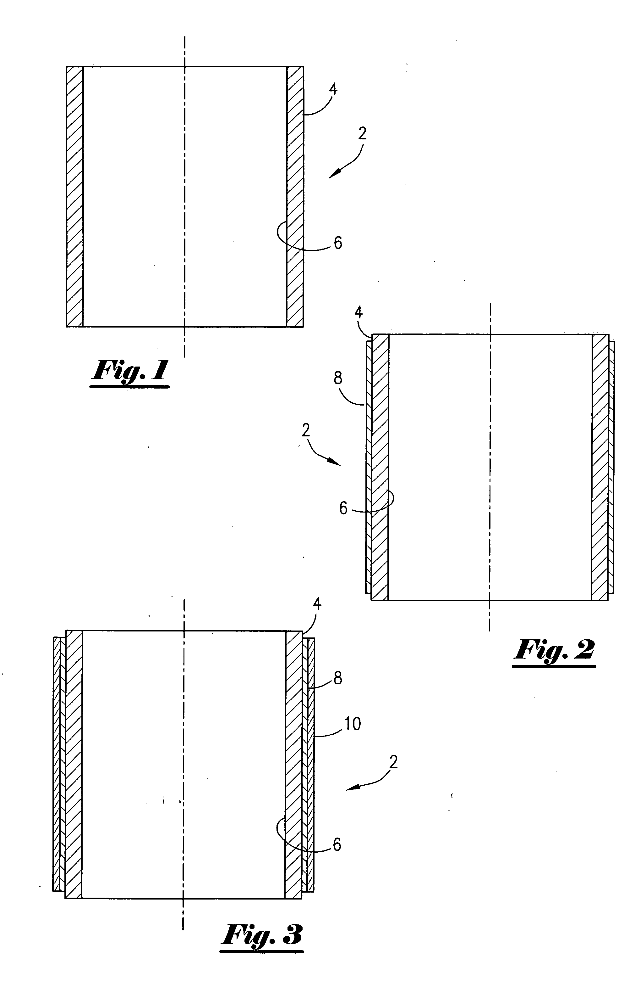
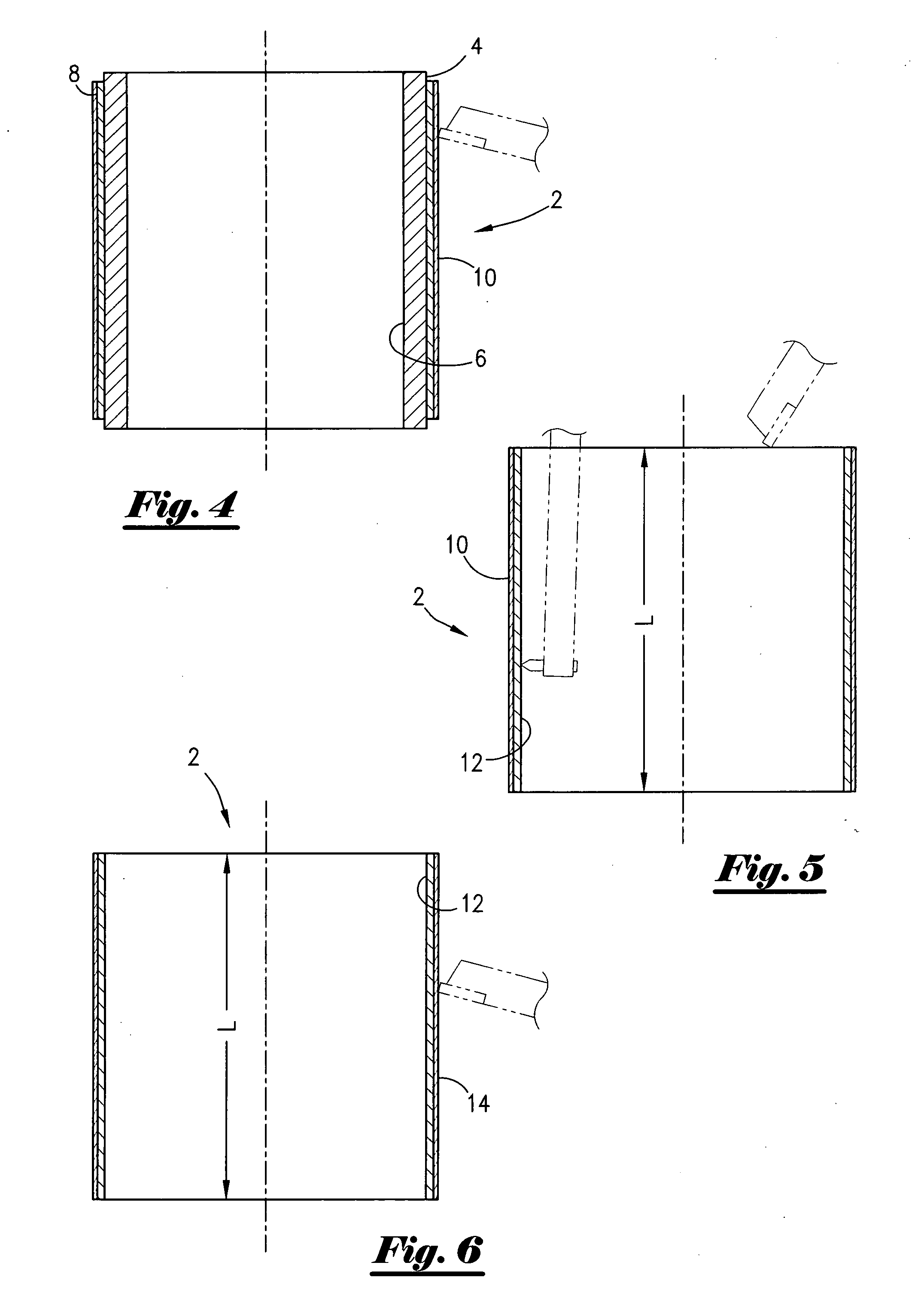
[0038]Referring now to FIG. 1, a cross-sectional view of a core sleeve 2 of the present invention is shown. The core sleeve 2 is made up from easy weldable and machinable material such as carbon steel in the preferred embodiment. The core sleeve 2 can also be constructed of a hard plastic. The core sleeve 2 has an outer diameter surface 4 and an inner diameter surface 6. As will be more fully set out, it is important to retain an accurate measurement of the outer diameter surface 4.

[0039]FIG. 2 is a cross-sectional view of the core sleeve 2 of FIG. 1 with a first coating applied thereto. More specifically, the operator will apply a layer of hard facing to the outer diameter surface 4. In the most preferred embodiment, the fusion process is utilized. An oxygen settling process or a laser process, both of which are commercially available, can be utilized in this hard facing step. In the most preferred embodiment, the laser process is utilized as set out below. Also in the most preferr...


PUM

PropertyMeasurementUnit
temperatureaaaaaaaaaa

Abstract

A process for manufacturing a bearing, which may be used in a tool within a bore hole. The process includes providing a tubular sleeve, applying a hard facing material on an outer surface of the tubular sleeve so that the hard facing material is fixed to the outer surface, and thereafter applying a material layer over the hard facing material so that the material layer is fixed to the hard facing material. The process further includes machining the material layer so that a portion of the material layer is removed, and then machining the inner surface so that only the hard facing material is left as an inner surface. The process further includes machining the inner and outer surfaces to form the bearing. The process further includes placing the bearing into a housing and inserting a mandrel into the bearing, where a hard coating of the mandrel abuts the bearing.

Description

CROSS-REFERENCE TO RELATED APPLICATION[0001]This continuation-in-part application claims the benefit of and priority to U.S. patent application Ser. No. 11 / 157,730, filed on Jun. 21, 2005, which is incorporated herein by reference.BACKGROUND OF THE INVENTION[0002]This invention relates to a wear surface, hard facing and process. More specifically, but not by way of limitation, this invention relates to a bearing used in surface facilities as well as down hole tools situated in a well bore, and a process for manufacturing the bearing.[0003]In the search for oil and gas, operators find it necessary to drill with a down hole tool that utilizes a down hole motor. As those of ordinary skill in the art will appreciate, the down hole motor includes a stationary housing and a concentrically disposed drive shaft, wherein the drive shaft has attached a bit means for boring a bore hole. The mandrel is rotated while concentrically located within the stationary housing. The friction created by t...

Claims


Application Information

Patent Timeline
Patent Type & Authority Applications(United States)
IPC IPC(8): B21K1/10
CPCB21D53/10Y10T29/49643F16C33/14E21B4/003F16C2220/62F16C2226/36F16C2220/70F16C2220/60F16C2220/82F16C2220/66F16C2226/12F16C2226/14F16C2352/00
Inventor VON GYNZ-REKOWSKI, GUNTHER HH.
Owner ASHMIN L C
Why Eureka
Try Eureka