Process for manufacturing a bearing

a manufacturing process and bearing technology, applied in the field of wear surface, can solve the problems of micro cracks forming in the hard facing material, and achieve the effects of more radial space, more loading capacity, and strong and ruggedness

Inactive Publication Date: 2011-02-08
RIVAL DOWNHOLE TOOLS LC
View PDF6 Cites 8 Cited by
  • Summary
  • Abstract
  • Description
  • Claims
  • Application Information

AI Technical Summary

Benefits of technology

[0013]An advantage of the present invention includes use of an outer diameter fusion process which eliminates the need for separate radial bearing systems and components. Another advantage is that the radial bearing product of the present invention is stronger and more rugged than prior art bearings. Yet another advantage is that the coating of the present invention will endure the severe temperature and shock loads imposed on down hole tools employed in boring holes in subterranean formations.
[0014]Another advantage of the present invention is that no radial bearing components are needed other than the housing and mandrel, which are an integral part of a radial bearing. Thus, a more robust mandrel and housing can be used since more radial space is available within the housing. Accordingly, more loading capacity and better reliability are experienced with the radial bearing of the present disclosure.
[0015]Yet another advantage is the rapid cooling of the hard facing material in one embodiment which allows for good particle distribution. Also, the rapid cooling process allows, in one preferred embodiment, for the formation of micro cracks in the hard facing material.
[0016]A feature of the present invention is that the materials used are applied to the outer diameter of a core sleeve. Another feature is that the outer diameter of the core sleeve, with the materials of the present invention applied thereto, can be machined with conventional tools. Still yet another feature is that the core sleeve, after application of the various materials, can be machined from the inner diameter using known milling and grinding tools. A feature of the present invention is that the starting tubular sleeve may be of sufficient length that it is possible for the operator, after the application of the various layers and machining of the outer and inner diameter, to cut the bearings into several predetermined lengths so that a plurality of bearings are produced, which will result in cost savings and lessen the manufacturing time.

Problems solved by technology

Additionally, the step of rapidly cooling may further include forming micro cracks within the hard facing material.

Method used


Image

  • Process for manufacturing a bearing
  • Process for manufacturing a bearing
  • Process for manufacturing a bearing

Examples


Embodiment Construction

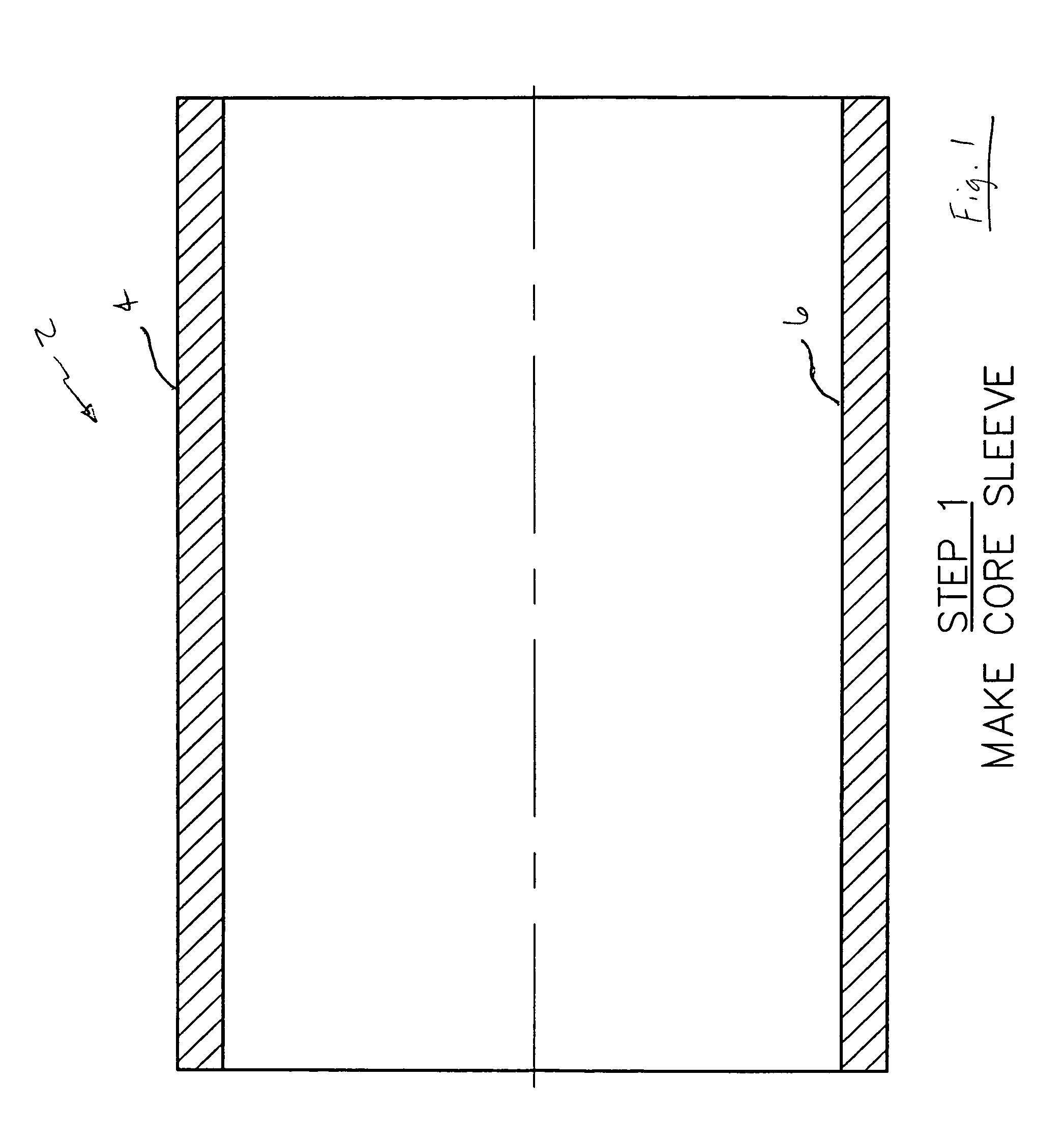
[0017]FIG. 1 is a cross-sectional view of a core sleeve of the present invention.

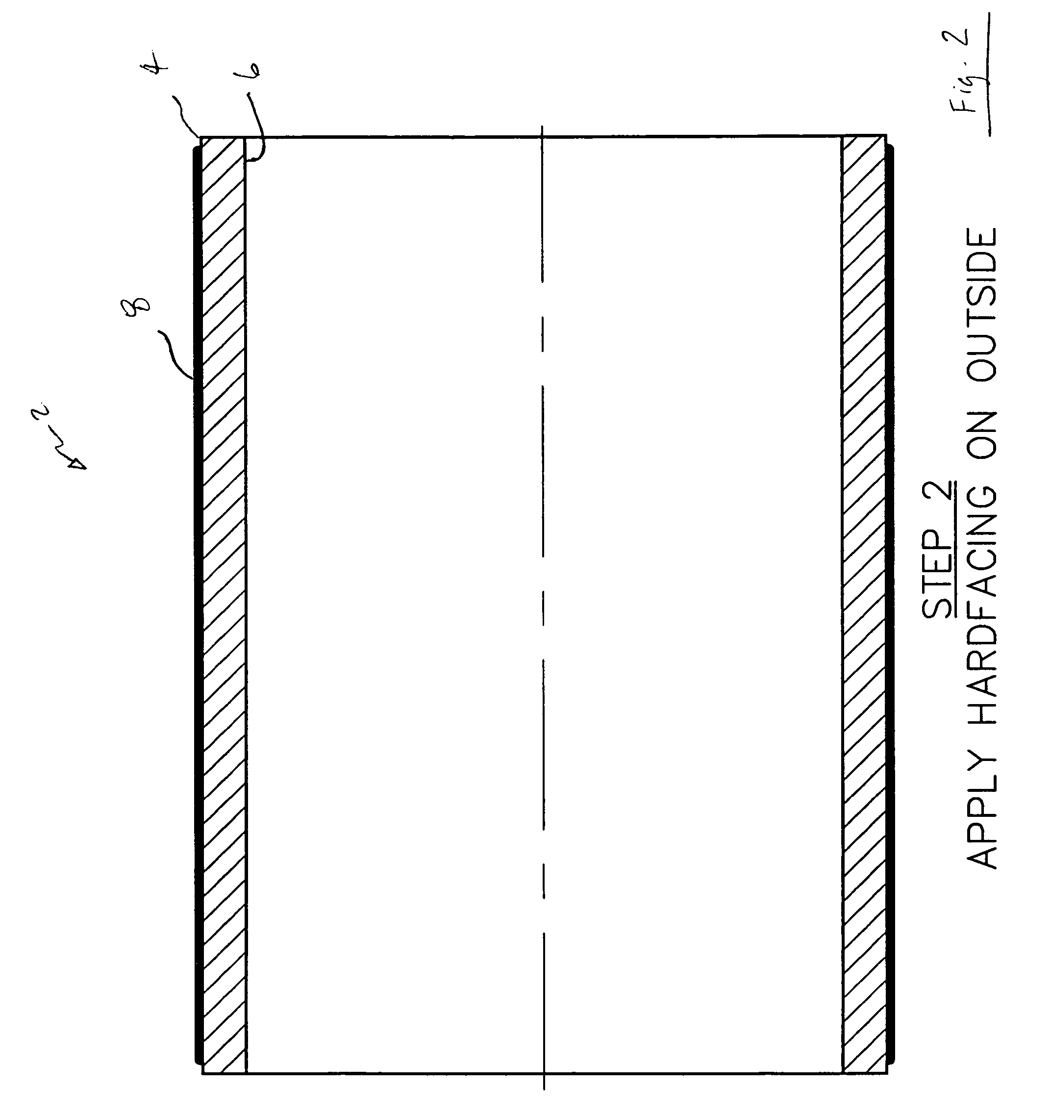
[0018]FIG. 2 is a cross-sectional view of the core sleeve of FIG. 1 with a first coating applied thereto.

[0019]FIG. 3 is a cross-sectional view of the core sleeve of FIG. 2 with a second coating applied thereto.

[0020]FIG. 4 is a cross-sectional view of the core sleeve of FIG. 3 having been machined on the outer diameter.

[0021]FIG. 5 is a cross-sectional view of the core sleeve of FIG. 4 having been machined on the inner diameter.

[0022]FIG. 6 is a cross-sectional view of the core sleeve of FIG. 5 having been machined on the outer diameter.

[0023]FIG. 7 is a cross-sectional view of the core sleeve of FIG. 6 having been machined on the inner diameter.

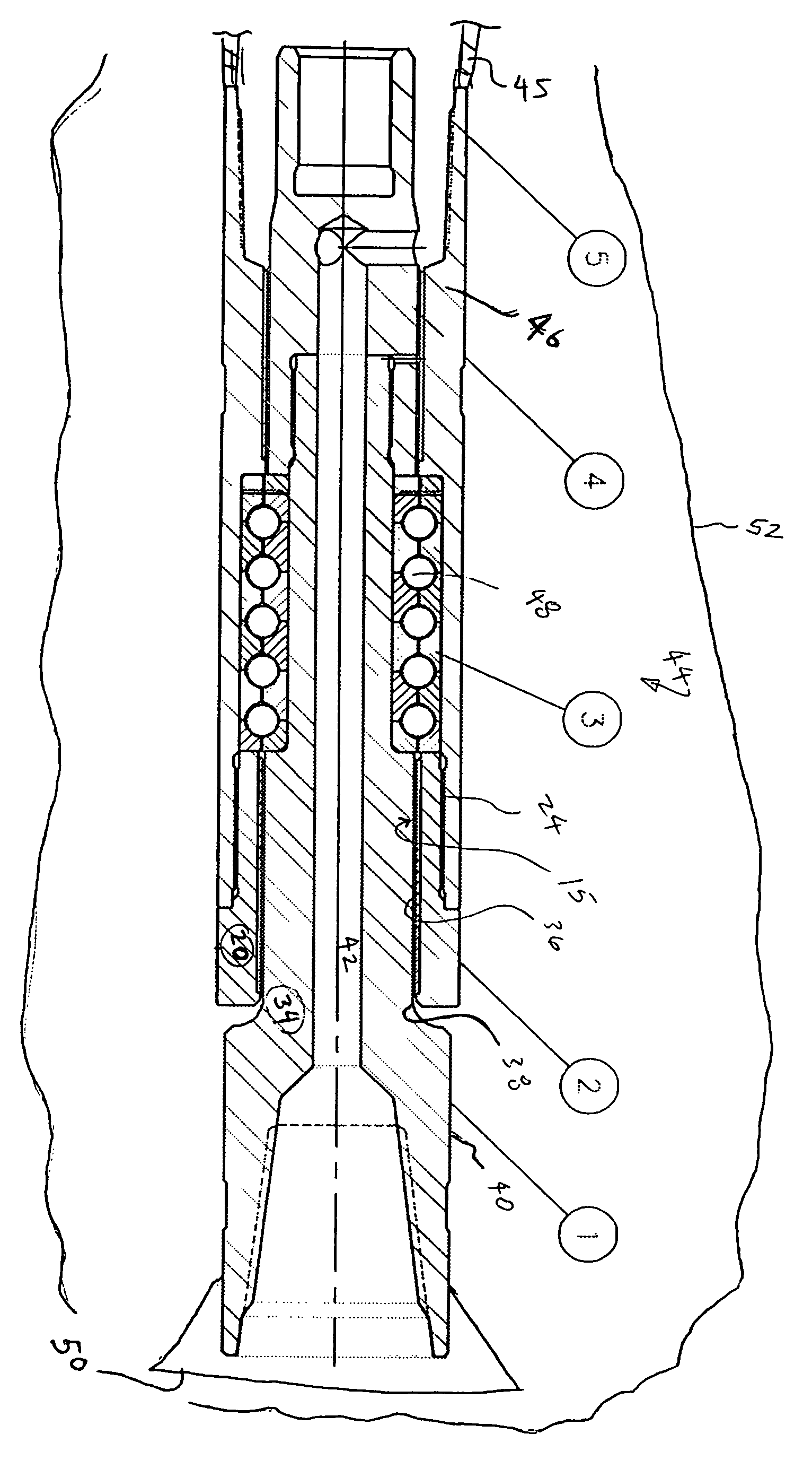
[0024]FIG. 8 is a partial cross-sectional view of the core sleeve of FIG. 7 concentrically disposed within a housing of a mud motor.

[0025]FIG. 9 is a partial cross-sectional view of a mandrel with a hard coating applied to the outer diameter.

[0026]FIG. 10 is a ...


PUM

PropertyMeasurementUnit
temperatureaaaaaaaaaa
temperaturesaaaaaaaaaa

Abstract

A process for manufacturing a bearing. The bearing may be used in a tool disposed within a bore hole. The process comprises providing a tubular sleeve and applying a hard facing material on the outer diameter of the tubular sleeve so that the hard facing material is fused onto the outer diameter, and thereafter applying a material layer on the outer diameter so that the material layer is fused onto the outer diameter. The method further includes machining the outer diameter so that a portion of the material layer is removed, and then machining the inner diameter so that only the hard facing material is left as an inner diameter. The method further includes machining the outer diameter and the inner diameter in order to form the bearing. In the most preferred embodiment, the method further includes placing the bearing into a housing, and inserting a mandrel into the bearing, and wherein a hard coating of the mandrel abuts the bearing. A mud motor for rotating a bit in a well bore is also disclosed.

Description

BACKGROUND OF THE INVENTION[0001]This invention relates to a wear surface, hard facing and process. More specifically, but not by way of limitation, this invention relates to a bearing used in surface facilities as well as down hole tools situated in a well bore, and a process for manufacturing the bearing.[0002]In the search for oil and gas, operators find it necessary to drill with a down hole tool that utilizes a down hole motor. As those of ordinary skill in the art will appreciate, the down hole motor includes a stationary housing and a concentrically disposed drive shaft, wherein the drive shaft has attached a bit means for boring a bore hole. The mandrel is rotated while concentrically located within the stationary housing. The friction created by the rotation of the stationary housing relative to the rotating mandrel can cause significant problems including wear, deformation and over-heating. Bearings have been developed for use in these tools. Prior art remedies include use...

Claims


Application Information

Patent Timeline
Patent Type & Authority Patents(United States)
IPC IPC(8): B21D53/10B23P13/04
CPCB21D53/10E21B4/003F16C33/14Y10T29/49746Y10T29/49643Y10T29/49996Y10T29/49636Y10T29/49655Y10T29/49668Y10T29/49664Y10T29/49677Y10T29/49705F16C2220/60F16C2220/66F16C2220/70F16C2220/82F16C2352/00E21B17/10
Inventor VON GYNZ-REKOWSKI, GUNTHER H H
Owner RIVAL DOWNHOLE TOOLS LC
Why Eureka
Try Eureka