Upper tool holder for press brake

a technology of upper tool and press brake, which is applied in the direction of manufacturing tools, shaping tools, metal-working apparatuses, etc., can solve the problems of insufficient fixation of the upper tool, the inability to close the clamp by the piston rod,

Active Publication Date: 2014-11-06
AMADA CO LTD
View PDF4 Cites 3 Cited by
  • Summary
  • Abstract
  • Description
  • Claims
  • Application Information

AI Technical Summary

Benefits of technology

[0012]In addition, it is preferable that the clamp has a lock pin contactable with the open restriction member, the lock pin is biased toward a direction for projecting an end thereof, a projected direction of the lock pin intersects with a slide direction of the open restriction member, the clamp is restricted from opening by a contact of an end surface of the lock pin with the open restriction portion, when the open res

Problems solved by technology

However, if the screw member is not brought back to its original state after exchanging the upper tool from beneath of the upper to

Method used


Image

  • Upper tool holder for press brake
  • Upper tool holder for press brake
  • Upper tool holder for press brake

Examples


Embodiment Construction

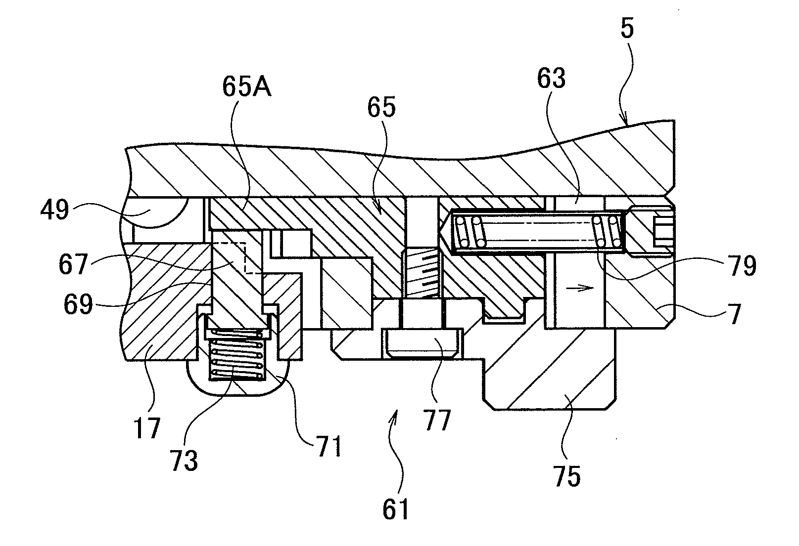
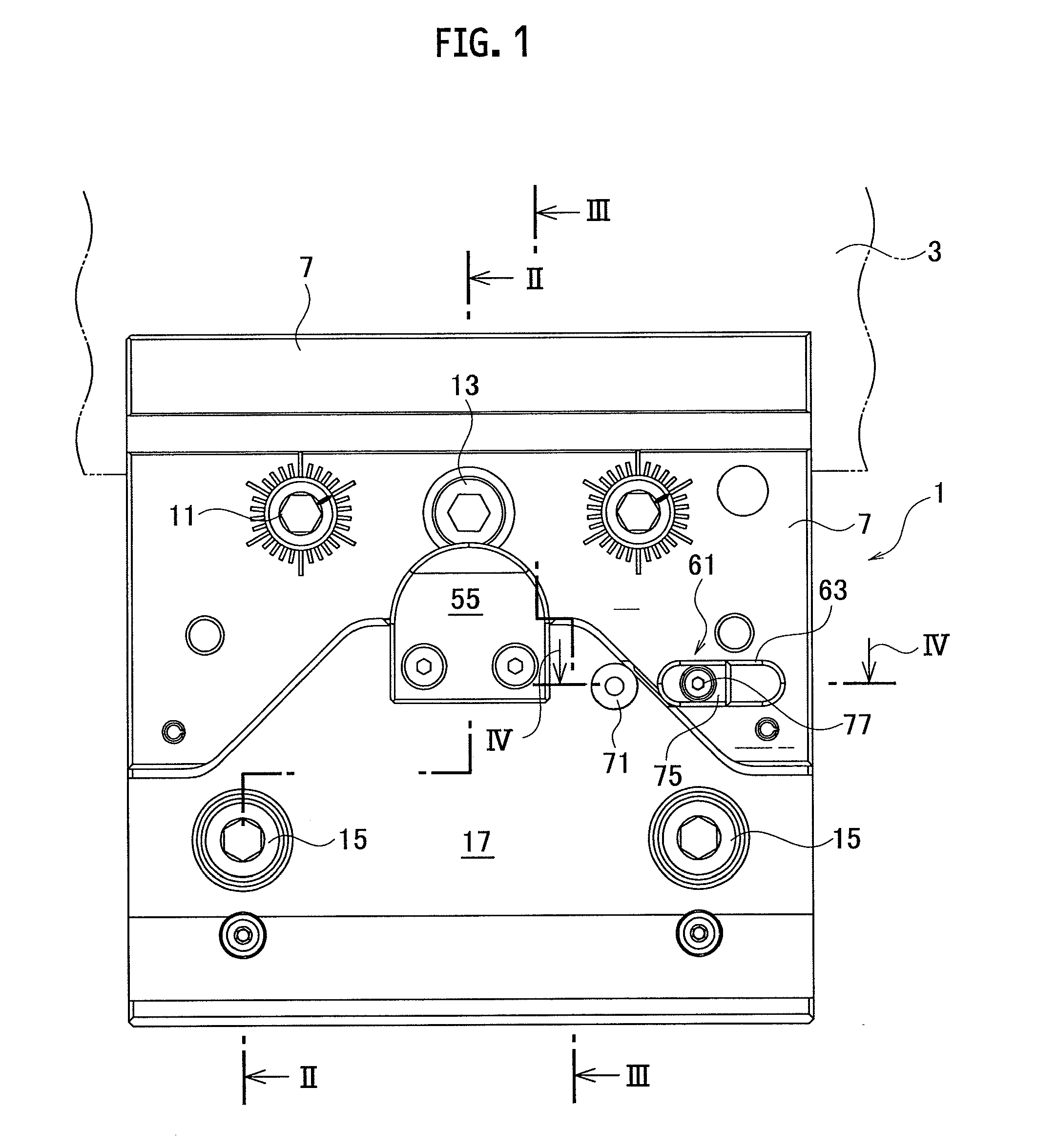
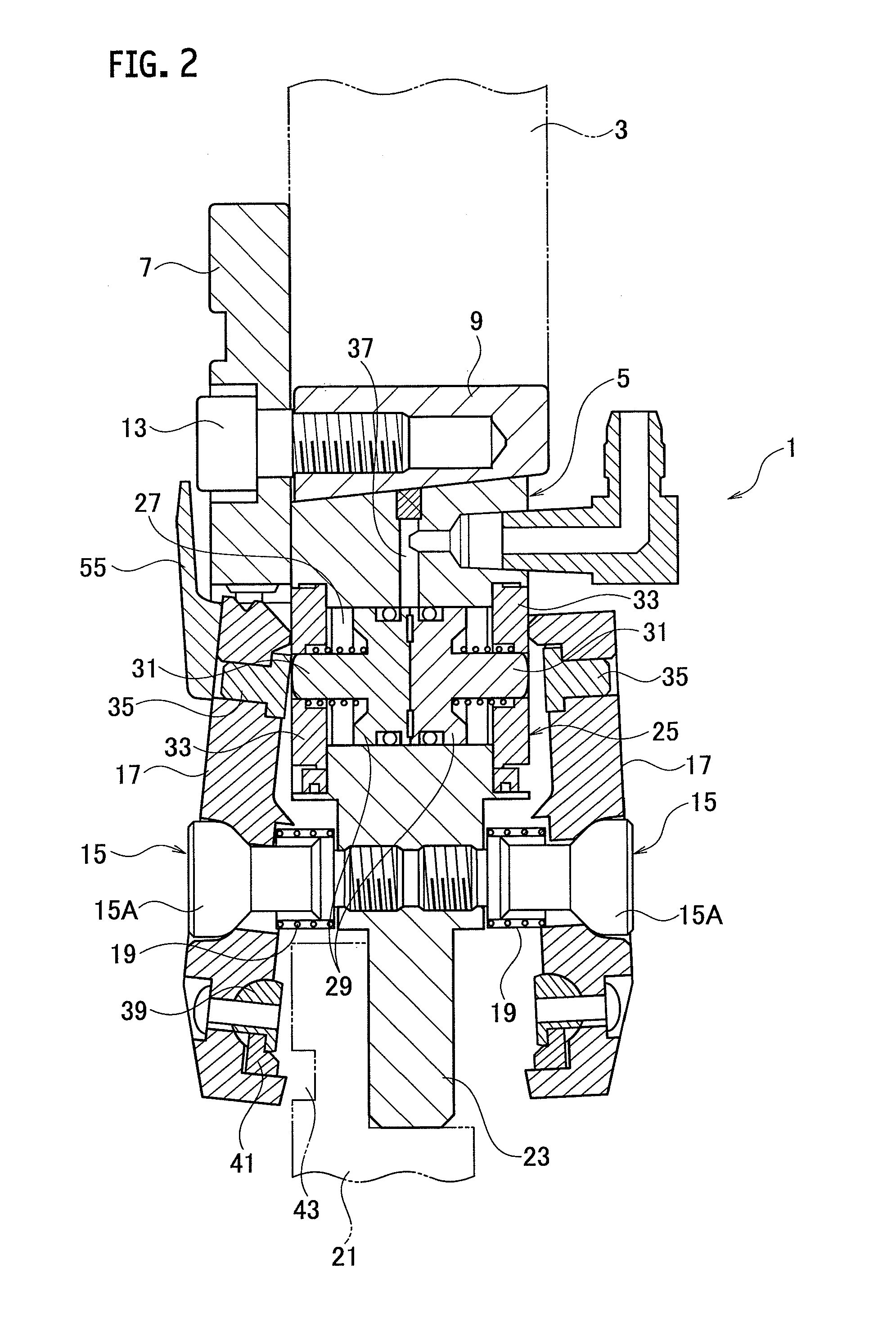
[0017]As shown in FIG. 1 and FIG. 2, an upper tool holder 1 according to the present embodiment includes a holder main body 5 that has an attachment portion to an upper table 3 of a press brake at its upper portion. An attachment plate 7 is attached to a front upper face of the holder main body 5 by plural pins (fixtures). The attachment plate 7 is fixed with the upper table 3 by a clamp jaw (not shown) attached to a front face of the upper table 3.

[0018]As shown in FIG. 2, au upper surface of the holder main body 5 is formed as a sloped surface slanted in a back-and-forth direction (a right-to-left direction in FIG. 2). A wedge member 9 having a sloped surface that planarly contacts with the upper surface of the holder main body 5 is provided above the holder main body 5. An upper surface of the wedge member 9 contacts planarly with a lower surface of the upper table 3. Ends of push bolts 11 (see FIG. 1) threadably mounted on the attachment plate 7 are contacted onto a front face o...


PUM


Abstract

An upper tool holder for holding an upper tool of a press brake exchangeably, includes a holder main body; an attachment portion provided on an upper portion of the holder main body; a support portion provided on a lower portion of the holder main body; a clamp provided swingably at a vertically intermediate position of the holder main body; an actuator that includes a pushing member for pushing the upper portion of the clamp to fix the upper tool with the support portion, and an open restriction member that has an open restriction portion for restricting the clamp. The open restriction member is provided at a position distanced from a pushed position of the upper portion of the clamp by the pushing member. According to the upper tool holder, the upper tool can be held firmly by the clamp.

Description

TECHNICAL FIELD[0001]The present invention relates to an upper tool holder for holding an upper tool of a press brake exchangeably.BACKGROUND ART[0002]An upper tool holder for holding an upper tool is provided at a lower portion of an upper table of a press brake. The upper tool holder includes a holder main body attached to the lower portion of the upper table, and a clamp attached to the holder main body. The clamp is swingably attached to the holder main body. In addition, the holder main body also includes a fluid pressure cylinder that has a piston rod for pushing an upper portion of the clamp forward. The fluid pressure cylinder is able to stroke the piston rod backward and forward. Then, at a pushed position of the clamp by an end of the piston rod, a screw member as a pushed member is screwed movably backward and forward (e.g. Patent Document 1 listed below).[0003]In the upper tool holder, a lower portion of the clamp is swung backward when the end of the piston rod of the f...

Claims


Application Information

Patent Timeline
IPC IPC(8): B21D5/02
CPCB21D5/0236B21D37/04B21D37/14
Inventor HAYASHI, SHIRO
Owner AMADA CO LTD
Why Eureka
Try Eureka