Control Valve Having a Disposable Valve Body

a control valve and valve body technology, applied in the field of fluid dispensing systems, can solve the problems of fluid within the flow control valve and/or other components of the fluid dispensing system to be unworkable, process may require more time and/or effort than desired, and the difficulty of cleaning these flow control valves is more difficult and/or time-consuming than desired

Active Publication Date: 2014-11-06
THE BOEING CO
View PDF3 Cites 29 Cited by
  • Summary
  • Abstract
  • Description
  • Claims
  • Application Information

AI Technical Summary

Benefits of technology

[0009]In another illustrative embodiment, a fluid dispensing system comprises a fluid source, an elongate member, an actuation device, a disposable valve body, a first element associated with the disposable valve body, and a second element associated with the disposable valve body. The fluid source holds a fluid having a viscosity within a selected range. The actuation device is configured to move the elongate member, which may be associated with the actuation device, linearly in a direction along an axis between an open position and a closed position. Th

Problems solved by technology

However, with the configurations of some currently available flow control valves, cleaning these flow control valves may be more difficult and/or time-consuming than desired.
When the fluid is a fluid having a higher viscosity, such as a sealant, halting the di

Method used


Image

  • Control Valve Having a Disposable Valve Body
  • Control Valve Having a Disposable Valve Body
  • Control Valve Having a Disposable Valve Body

Examples


Embodiment Construction

[0029]The illustrative embodiments recognize and take into account different considerations. For example, the illustrative embodiments recognize and take into account that it may be desirable to have a fluid dispensing system having a flow control valve that can be easily cleaned. Further, the illustrative embodiments recognize and take into account that it may be desirable to have a fluid dispensing system capable of dispensing fluid with a greater precision as compared to some currently available fluid dispensing systems.

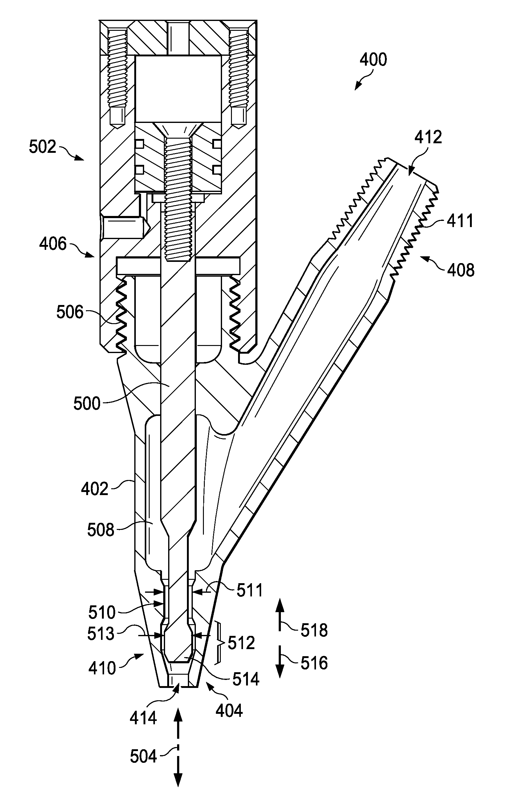
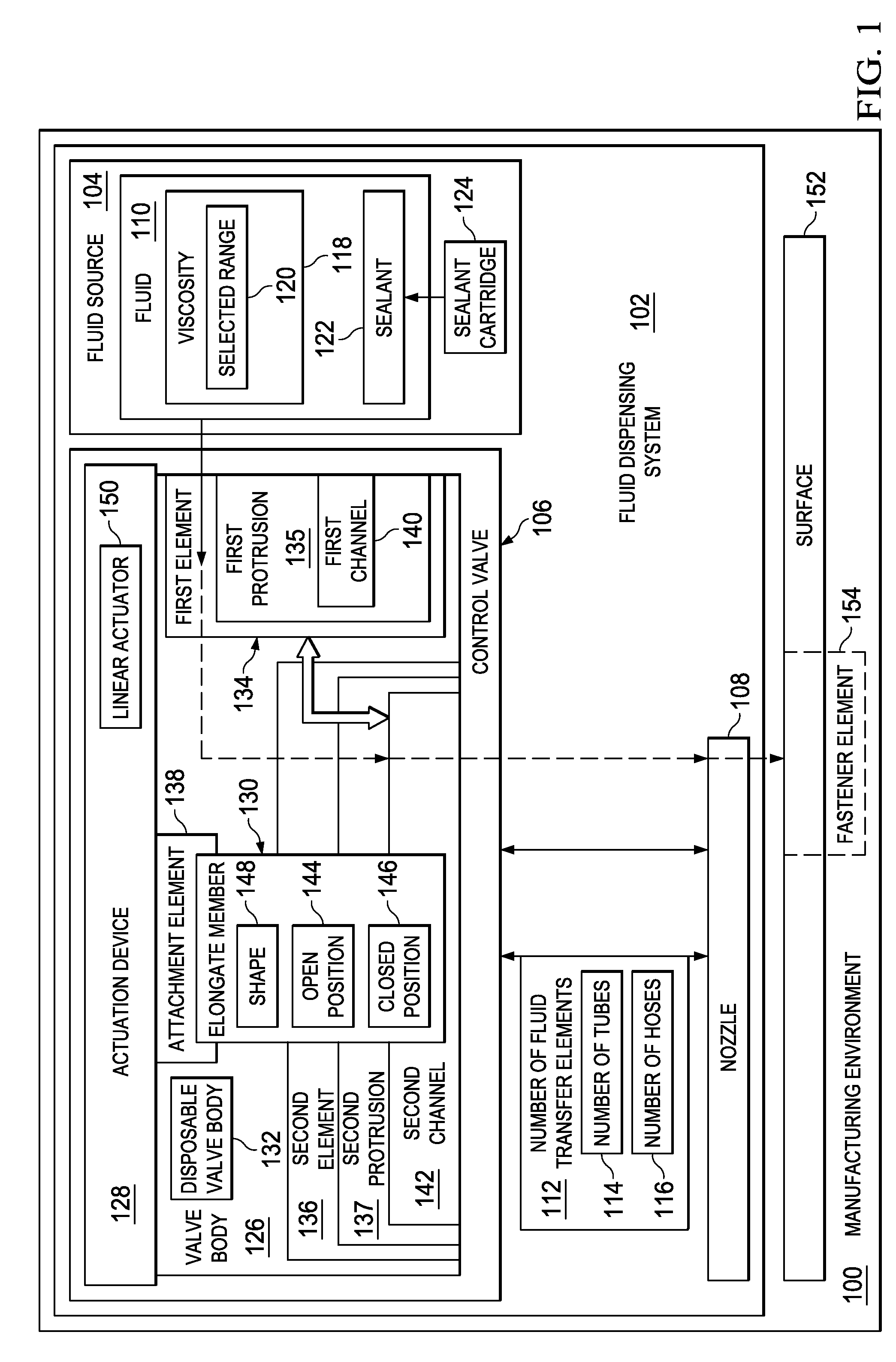
[0030]Thus, the illustrative embodiments provide a fluid dispensing system having a control valve with a disposable valve body. This disposable valve body may be removed from the control valve to allow access to the internal wetted portions of the control valve. The disposable valve body may then be discarded after use allowing for the inner portion of the control valve to be accessible and cleaned with ease. A different disposable valve body may then be attached ...


PUM


Abstract

A method and apparatus for controlling a flow of a fluid through a valve. In one illustrative embodiment, an apparatus comprises an elongate member, an actuation device, and a valve body. The actuation device is configured to move the elongate member, which may be associated with the actuation device, between an open position and a closed position. The valve body is configured for attachment to the actuation device such that the elongate member is positioned within the valve body. Fluid that flows into the valve body from a fluid source is allowed to flow out of the valve body when the elongate member is in the open position.

Description

BACKGROUND INFORMATION[0001]1. Field[0002]The present disclosure relates generally to fluid dispensing systems and, in particular, to a control valve for a fluid dispensing system. Still more particularly, the present disclosure relates to an apparatus and method for controlling a flow of fluid through a control valve having a disposable housing.[0003]2. Background[0004]Fluid dispensing systems may be used to dispense fluids such as, for example, without limitation, sealant, adhesive, water, oil, and other types of fluids. In one illustrative example, a fluid dispensing system may be used to dispense sealant over an interface between two components. The interface may be, for example, without limitation, the interface between a first panel and a second panel, the interface between a fastener element and a surface, a joint, a seam, or some other type of interface.[0005]Some currently available fluid dispensing systems may route a fluid, such as sealant, to a flow control valve that is...

Claims


Application Information

Patent Timeline
IPC IPC(8): B05C5/02
CPCB05C5/0225B05B1/3046B05B1/3073F16K3/24F16K21/00F16K23/00F16K31/00F16K31/122Y10T137/0318Y10T137/0491Y10T137/87676
Inventor TOPF, RICHARD PHILIPGUIRGUIS, MARTIN HANNA
Owner THE BOEING CO
Why Eureka
Try Eureka