Directional touch remote

a remote control and directional technology, applied in the field of remote control, can solve the problems of lacked in the way of functionality, accidental commands are too often given, and devices become more complex

Active Publication Date: 2014-12-04
APPLE INC
View PDF6 Cites 4 Cited by
  • Summary
  • Abstract
  • Description
  • Claims
  • Application Information

AI Technical Summary

Benefits of technology

The present patent describes methods and arrangements for remotely controlling a device with a touch screen using a graphical user interface (GUI) with multiple contexts. The device can receive and interpret data characterizing touch events and translate it into a list of available commands, which can be acted upon by the device. The same touch can affect different actions in different interface contexts, and a method for remotely controlling an application on the same or different remote devices is also provided. The data can be received and updated with available events based on the context and selection of an event for the associated GUI.

Problems solved by technology

As devices become more complex so do the remotes that control them.
The earliest remotes were effective for their simplicity, but as technology progressed they lacked in the way of functionality.
Such remotes often require close study to learn the function of a button and frequently have buttons so small that accidental commands are too often given.
Even with shapes or textures, too often a user's focus is taken off of the remotely controlled device and focused on the remote—an undesirable consequence of a complicated interface.
Since touch screens do not have tactile feedback that allows the user to confirm which selection is made, the user must visually confirm the selection, which is undesirable.
Further these remotes have the drawback that they can sometimes operate too slowly for a remote application owing to the back and forth communication between the remote and the remotely controlled device.
While these remotes can be operated by viewing the remotely controlled device instead of the remote itself, they can require too much user effort to enter a command.

Method used


Image

  • Directional touch remote
  • Directional touch remote
  • Directional touch remote

Examples


Embodiment Construction

[0028]Various embodiments of the disclosed methods and arrangements are discussed in detail below. While specific implementations are discussed, it should be understood that this is done for illustration purposes only. A person skilled in the relevant art will recognize that other components, configurations, and steps may be used without parting from the spirit and scope of the disclosure.

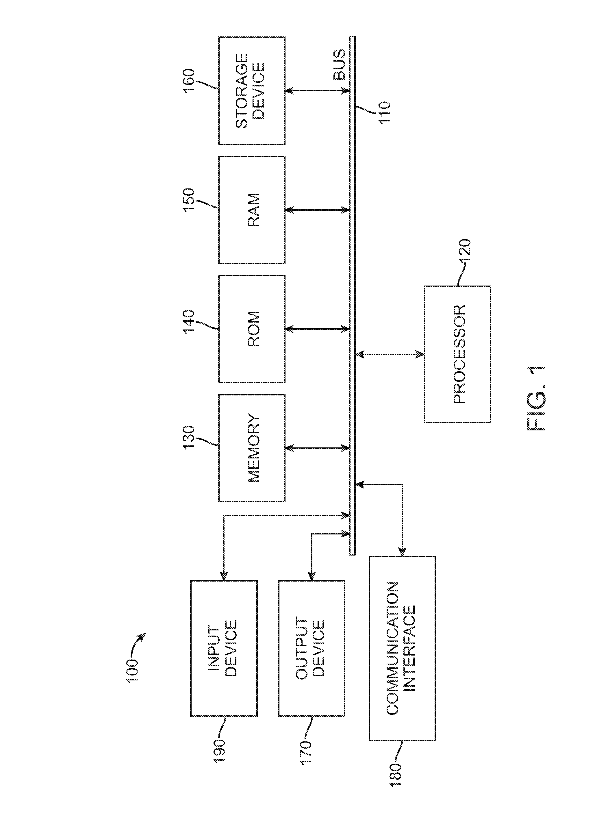
[0029]With reference to FIG. 1, a general-purpose computing device 100 which can be portable or stationary is shown. The general-purpose computing device can be suitable for carrying out the described embodiments or in some embodiments two or more general-purpose computing devices can communicate with each other to carry out the embodiments described below. The general purpose computing device 100 is shown including a processing unit (CPU) 120 and a system bus 110 that couples various system components including the system memory such as read only memory (ROM) 140 and random access memory (RAM) 150...


PUM


Abstract

The present system and method is particularly useful for remotely controlling a device having one or more menus via a remote touch interface having at least an unstructured primary input area. A user can provide inputs to a touch interface without needing to view the interface and yet still achieve the desired response from the remotely controlled device. The primary input area of the touch interface may or may not have a background display, such as on a touch screen, but the primary input area of the touch interface should be unstructured and should not have independently selectable items, buttons, icons or anything of the like. Since the touch interface is unstructured, the user does not have to identify any selectable buttons. Instead the user can input a gesture into the interface and watch the remotely controlled device respond. The system does not provide any other visual confirmation.

Description

PRIORITY CLAIM[0001]This application is a continuation of U.S. patent application Ser. No. 12 / 434,556, entitled “Directional Touch Remote”, filed May 1, 2009, the entirety of which is incorporated herein by reference.TECHNICAL FIELD[0002]The present technology is related to remote controls and specifically touch device remote controls.INTRODUCTION[0003]As devices become more complex so do the remotes that control them. The earliest remotes were effective for their simplicity, but as technology progressed they lacked in the way of functionality. Today it is common to find remotes with upwards of fifty buttons, each often having multiple functions. Such remotes often require close study to learn the function of a button and frequently have buttons so small that accidental commands are too often given.[0004]Buttons are convenient because they provide tactical feedback of giving a command and in some cases a select few buttons can even have a different feel or shape to facilitate the ab...

Claims


Application Information

Patent Timeline
Patent Type & Authority Applications(United States)
IPC IPC(8): H04L29/08G06F3/0482G06F3/0488H04M1/725H04M1/72415
CPCH04L67/025G06F3/0488G06F3/0482H04M1/72533G06F3/04883H04M2250/22H04N21/42224H04N21/4227H04N21/431H04N21/47H04N21/482H04N21/4222H04N21/64322H04N21/41265H04N21/42204H04M1/72415G06F9/451
Inventor BRODERSEN, RAINERCANNISTRARO, ALANROBBIN, JEFFREY L.LINDLEY, GREGORY CHARLES
Owner APPLE INC
Why Eureka
Try Eureka