
Systems and Methods for Providing Constant Warning Time At Crossings

a technology of constant warning time and crossing, applied in the direction of railway traffic control, traffic gates, railway signalling and safety, etc., can solve the problems of long warning time, inability to accurately predict the time of crossing, and inability to provide constant warning time at crossings

Active Publication Date: 2014-12-11
GENERAL ELECTRIC CO
View PDF14 Cites 20 Cited by
  • Summary
  • Abstract
  • Description
  • Claims
  • Application Information

AI Technical Summary

Benefits of technology

The patent describes a system, method, and apparatus for controlling vehicles at crossings in order to prevent collisions and improve safety. The system includes a device on a first vehicle that determines the timing of when the first vehicle will pass through a crossing and sends this information to a remote crossing module on the second vehicle. The remote crossing module receives the timing information and uses it to impede the second vehicle's travel through the crossing. This allows for safer travel through crossings and reduces the risk of accidents.

Problems solved by technology

In some systems, for example rail systems that use catenaries or third rails to provide energy to rail vehicles, electrical interference may be too high for predictor systems to function accurately.
Long warning times are undesirable because of the unnecessary delay caused to motorists, and also because overly long warning times may tempt impatient motorists to drive around crossing gates and / or disregard audible or visible warnings if the motorists do not see any trains approaching after some period of time.
Traditional predictor track circuits are limited by practical considerations to a range extending a given distance from a crossing.
In such systems, crossings will frequently activate earlier than desired, resulting in overly long waiting periods, and resulting in inconsistent wait times for motorists.
Such systems also fail to address issues resulting from relatively slower speeds.

Method used


Image

  • Systems and Methods for Providing Constant Warning Time At Crossings
  • Systems and Methods for Providing Constant Warning Time At Crossings
  • Systems and Methods for Providing Constant Warning Time At Crossings

Examples


Embodiment Construction

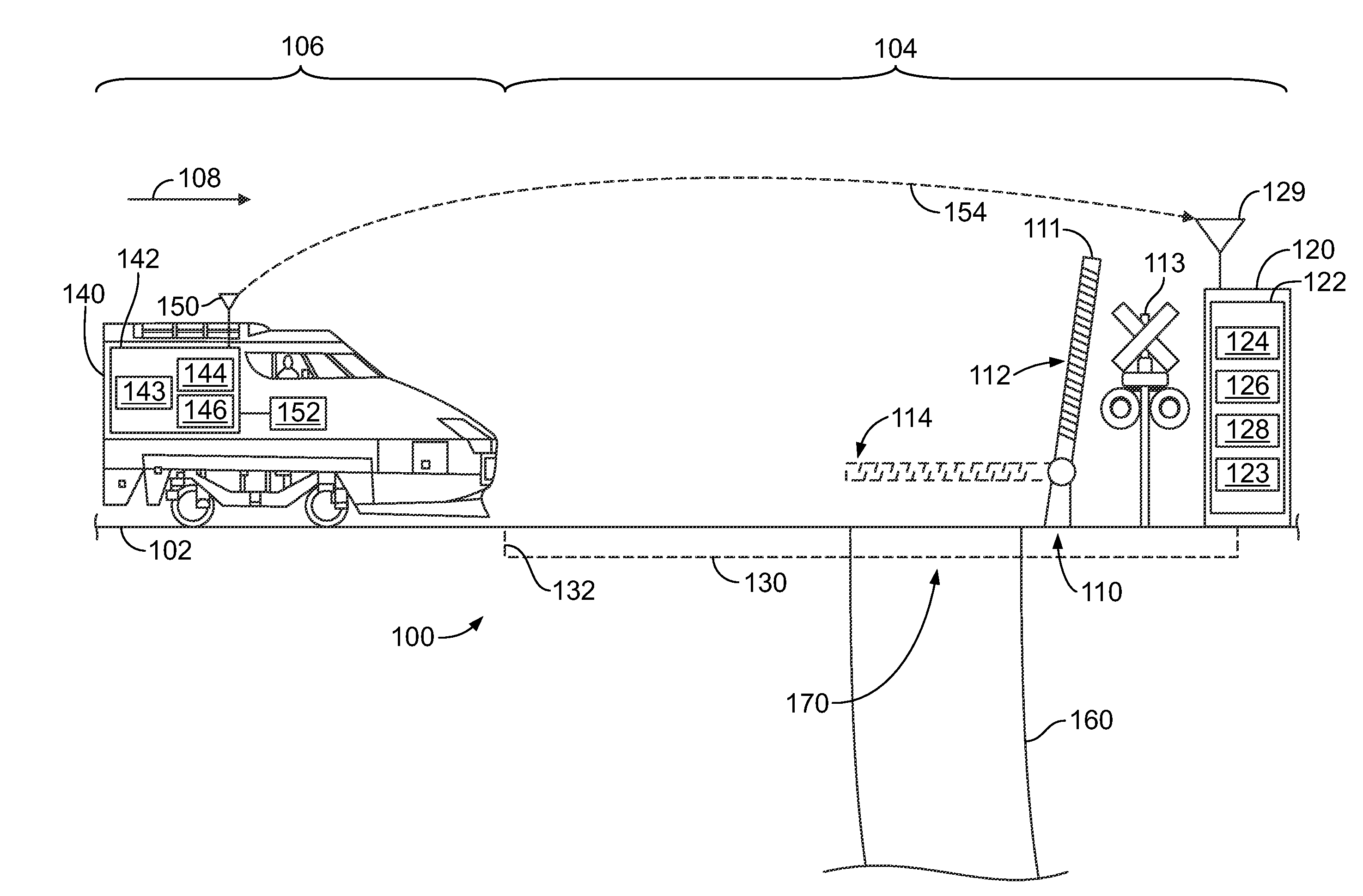
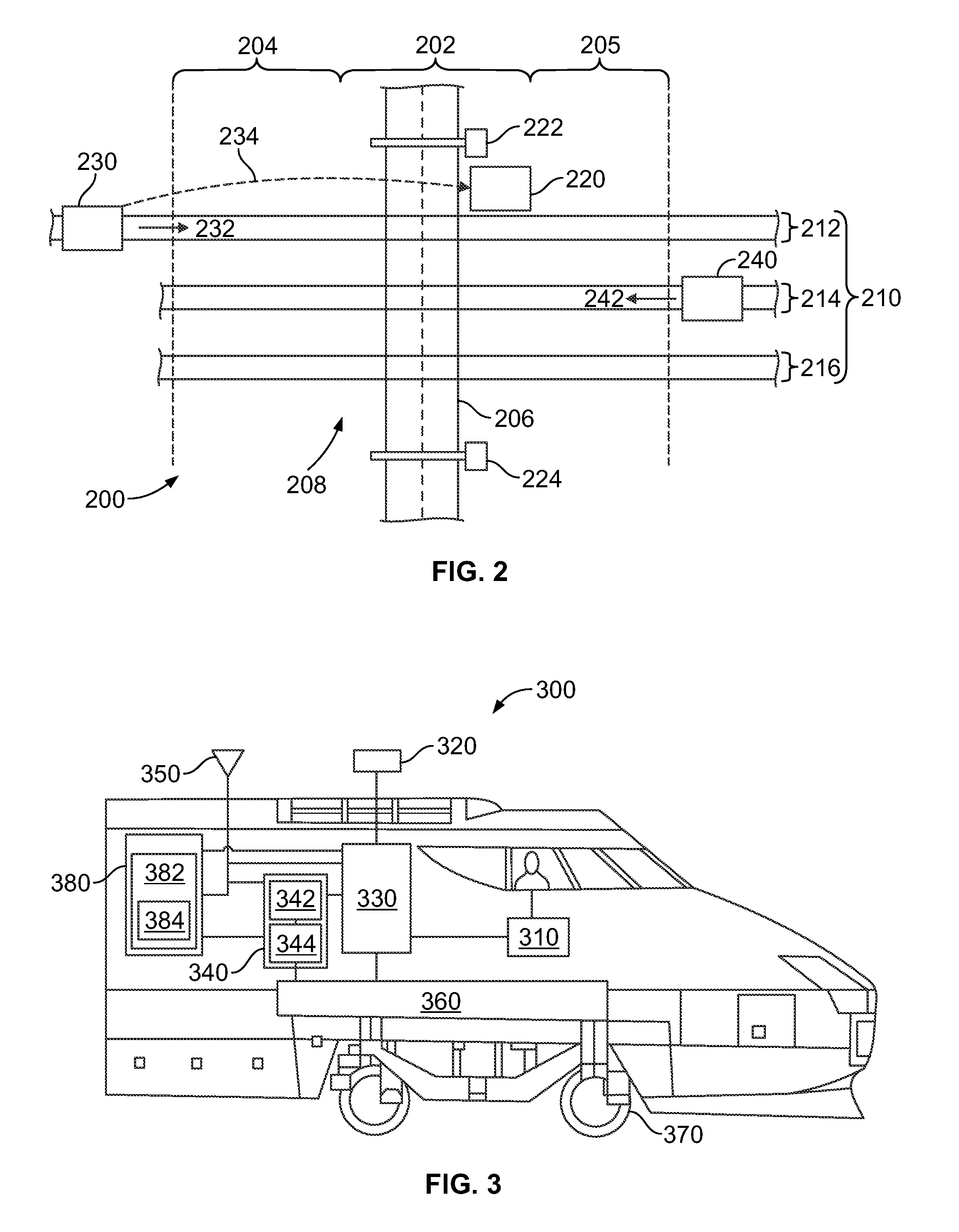
[0015]One or more embodiments of the inventive subject matter described herein provide systems and methods for improved operation of crossings for transportation systems, such as crossings associated with an intersection between a rail system and a road or highway system. In various embodiments, an onboard system is provided that is configured to control movement of a rail vehicle and to communicate with a remote crossing module, such as wayside equipment controlling the crossing. The control systems for the rail vehicle, for example, may be configured to be compatible with Positive Train Control (PTC) systems utilized in the United States. In various embodiments, bidirectional communications between onboard equipment and wayside equipment may be used to activate and deactivate crossing warning (or closing) systems only when necessary to provide a substantially consistent amount of warning time. In various embodiments, an onboard system is configured to communicate an arrival time a...


PUM


Abstract

A system includes a determination module and a communication module. The determination module is configured to be located onboard a first vehicle configured to travel along a first route including a crossing corresponding to an intersection of the first route with a second route. The determination module is configured to be communicatively coupled with a remote crossing module. The determination module is configured to determine, based on a speed of the first vehicle, timing information corresponding to a time at which the first vehicle will travel proximate to the crossing on the first route. The communication module is configured to transmit the timing information to the remote crossing module. The timing information includes a reference time configured as an absolute time corresponding to a time for impeding travel of a second vehicle along the second route through the crossing.

Description

FIELD[0001]Embodiments of the subject matter described herein relate to vehicle location systems and methods, and more particularly, to systems and methods for providing constant or consistent warning times at crossings.BACKGROUND[0002]A rail vehicle transportation system may include tracks over which rail vehicles travel. These tracks may cross routes of other transportation systems, such as road or highway systems over which automobile traffic may pass. To warn automobiles, crossing gates may be provided at locations where the tracks intersect roads, with the crossing gates configured to warn motorists and inhibit automobiles from crossing the tracks while a rail vehicle is traveling on the tracks at or near the crossing.[0003]Some known railroad crossings use a warning predictor track circuit that detects motion of a train towards the crossing. Warning predictors may calculate the time of train arrival to the crossing based on the detected motion, and activate the crossing warnin...

Claims


Application Information

Patent Timeline
IPC IPC(8): B61L29/04
CPCB61L29/04B61L29/22B61L29/32
Inventor FRIES, JEFFREY MICHAELBAKER, JEFFREYWEINGARTNER, ARIC ALBERTSTEFFEN, II, MICHAELHERLOCKER, JESSE LEESHIELDS, WILLIAM
Owner GENERAL ELECTRIC CO
Learn More