Stereoscopic display device

a display device and stereoscopic technology, applied in the field of stereoscopic display devices, can solve the problems of not being able to achieve 3d display, and the patent also fails to describe the effect of 2d display while the device is being used

Inactive Publication Date: 2014-12-11
SHARP KK
View PDF2 Cites 5 Cited by
  • Summary
  • Abstract
  • Description
  • Claims
  • Application Information

AI Technical Summary

Benefits of technology

[0006]An object of the present invention is to provide a stereoscopic display device that can be switched among 2D displa

Problems solved by technology

This display device may be switched between 2D image display mode and mirror mode; however, it is not capable of real

Method used


Image

  • Stereoscopic display device
  • Stereoscopic display device
  • Stereoscopic display device

Examples


first embodiment

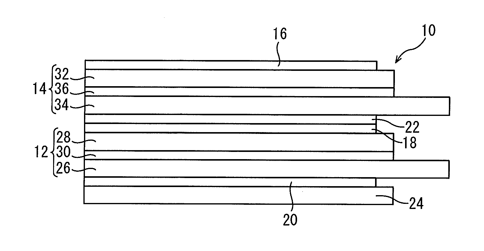
[0036]FIG. 1 shows a stereoscopic display device 10 of a first embodiment of the present invention. The stereoscopic display device 10 includes a display panel 12, a switch liquid crystal panel 14, absorptive polarizers 16, 18 and 20, a reflective polarizer 22 and a backlight 24.

[0037]The display panel 12 is a liquid crystal panel. The display panel 12 includes an active-matrix substrate 26, a counter substrate 28 and a liquid crystal layer 30 enclosed between these substrates 26 and 28. In the display panel 12, any operating mode of liquid crystal may be used.

[0038]The display panel 12 includes a plurality of pixels. The pixels may be arranged in a matrix, for example. The region in which the pixels are provided forms the display region of the display panel 12.

[0039]Each pixel may include a plurality of sub-pixels. The sub-pixels may be, for example, a red sub-pixel, green sub-pixel and blue sub-pixel. The sub-pixels may further include sub-pixels of other colors.

[0040]In the displ...

second embodiment

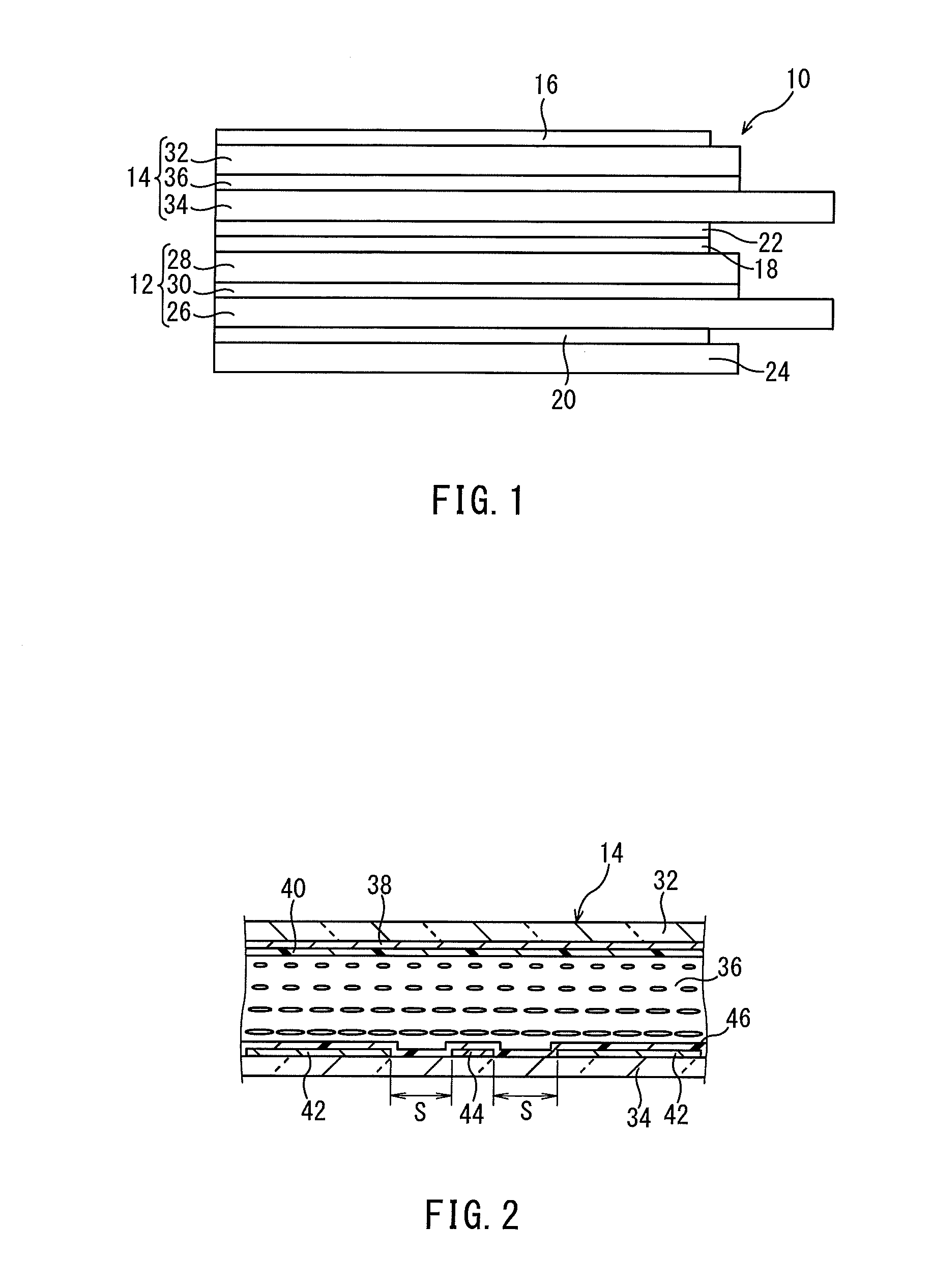
[0126]In the present embodiment, as shown in FIG. 13, each auxiliary electrode 44 includes a plurality of openings (transparent regions) 64. The openings 64 are arranged in a longitudinal direction of the auxiliary electrode 44. It is desirable that the openings 64 be arranged at regular intervals. In the implementation shown in FIG. 13, the openings 64 are circular in shape; however, the openings 64 are not limited to a particular shape. The size (width) of each opening 60 may be, for example, in the range of 10 to 50 μm. The sum of the areas of all openings 60 and gaps S is preferably 20% or less of the surface area of the active area of the switch liquid crystal panel 14 (i.e. the area covered by the common electrode 38 in the present embodiment). Thus, 2D image display and good mirror properties may be realized at the same time.

[0127]The use of such auxiliary electrodes 44 will eliminate the necessity to increase the size of the gaps S between the driving electrodes 42 and auxil...

application example of second embodiment

[0128]In the present application example, as shown in FIG. 14, a single opening 66 is formed in each auxiliary electrode 44. Such an opening 66 will also provide the intended effects.


PUM


Abstract

The objective is to provide a stereoscopic display device that can be switched among 2D display mode, 3D display mode and mirror mode, where 2D display may be realized even while the device is staying in mirror mode. The device includes: a display panel (12); a switch liquid crystal panel (14); an absorptive polarizer (16); and a reflective polarizer (22). The switch liquid crystal panel is located closer to the viewer than the display panel is. The absorptive polarizer is located closer to the viewer than the switch liquid crystal panel is. The reflective polarizer is located between the display panel and the switch liquid crystal panel. The reflective polarizer passes those components of light entering the reflective polarizer that are parallel to the transmission axis (L6) while reflecting those components that are perpendicular to the transmission axis. At least one of the substrates (32, 34) includes a transparent region (58) capable of passing light from the display panel.

Description

TECHNICAL FIELD[0001]The present invention relates to a stereoscopic display device with a switch liquid crystal panel, and more particularly, to a stereoscopic display device with a mirror capability.BACKGROUND ART[0002]There is a growing need for display devices with various additional values. One example is a stereoscopic display device that allows the viewer to see stereoscopic video without special glasses. One known scheme for realizing this uses a parallax barrier.[0003]A parallax barrier based stereoscopic display device may include, for example, a display panel and a switch liquid crystal panel, where the display panel displays a stereoscopic image and the switch liquid crystal panel forms a parallax barrier that divides the stereoscopic image into sub-images. The parallax barrier includes apertures that pass light and light-shielding portions that block light. In the parallax barrier, apertures and light-shielding portions are arranged alternately.[0004]Such a parallax bar...

Claims


Application Information

Patent Timeline
IPC IPC(8): G02B27/26G02F1/1335G02B30/25
CPCG02F1/133536G02B27/26G02F1/133528G02B30/25G02F1/133531H04N13/31H04N13/356
Inventor MURAO, TAKEHIROYOSHINO, TAKUTOFUKUSHIMA, HIROSHITAKATANI, TOMOO
Owner SHARP KK
Why Eureka
Try Eureka