Electronic correction based on eye tracking

Active Publication Date: 2014-12-11
SONY COMPUTER ENTERTAINMENT INC
View PDF1 Cites 73 Cited by
  • Summary
  • Abstract
  • Description
  • Claims
  • Application Information

AI Technical Summary

Problems solved by technology

Other HMDs, however, allow the user only to see the displayed images, which is to say that they obscure the real world environment surrounding the user.

Method used


Image

  • Electronic correction based on eye tracking
  • Electronic correction based on eye tracking
  • Electronic correction based on eye tracking

Examples


Embodiment Construction

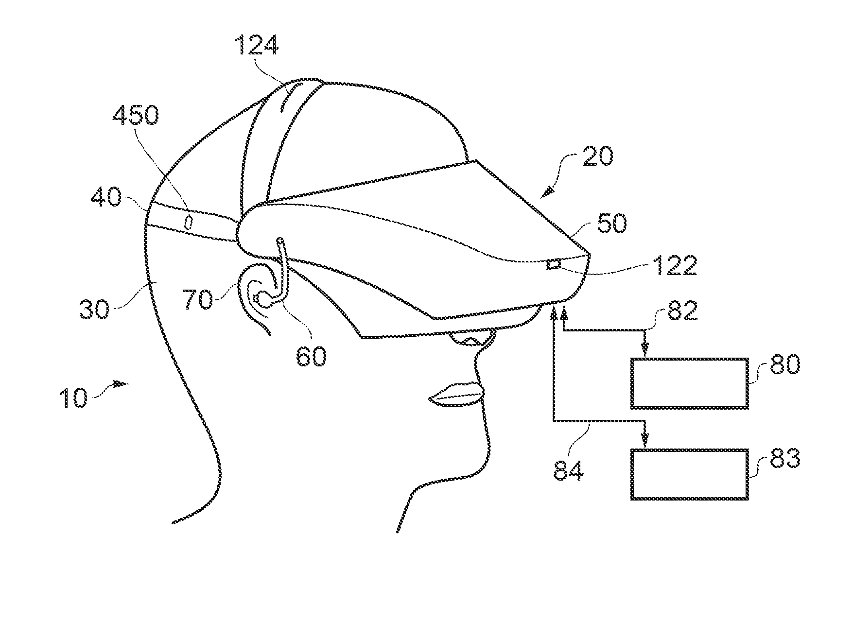
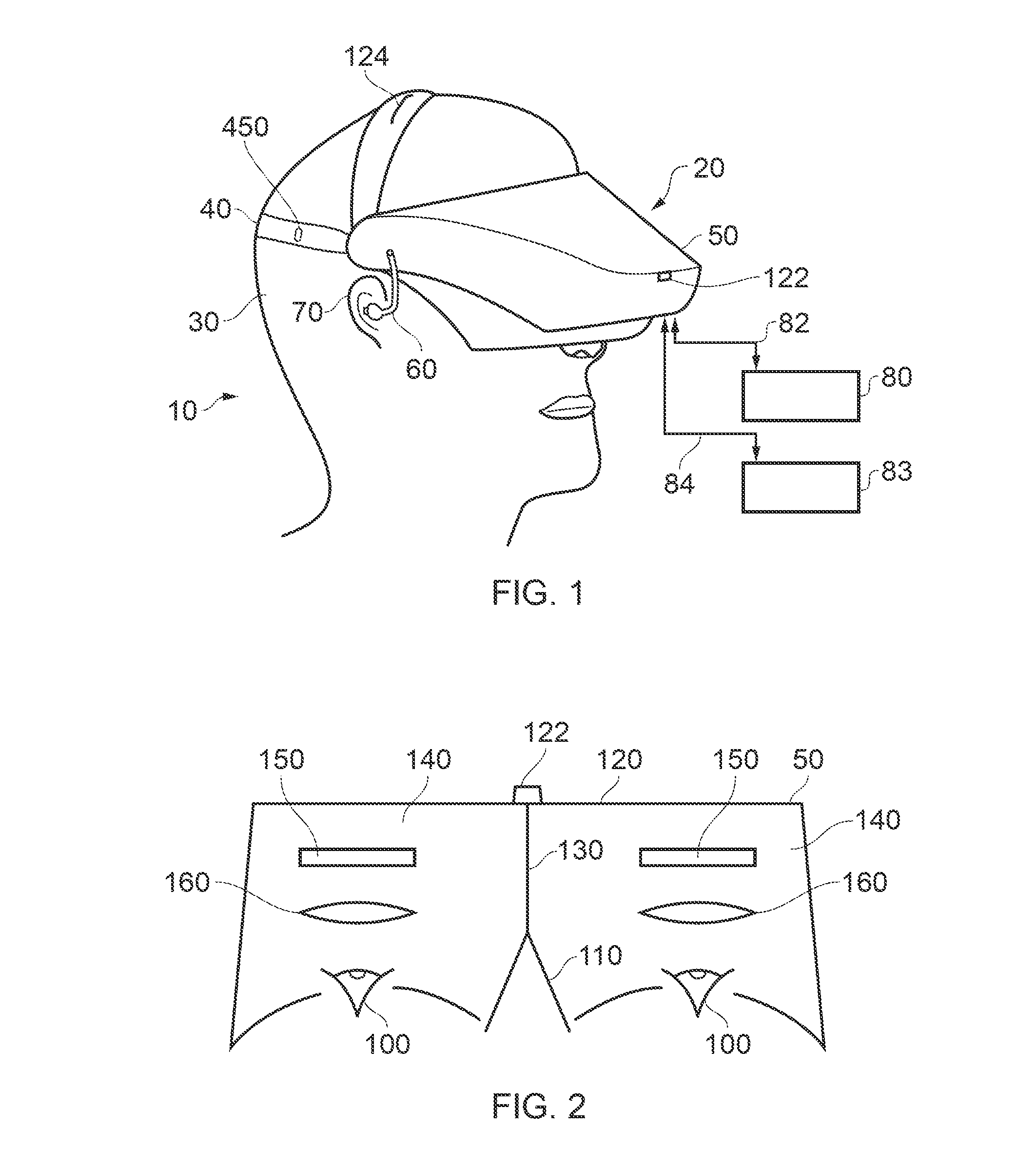
[0033]Referring now to FIG. 1, a user 10 is wearing an HMD 20 (as an example of a generic head-mountable apparatus—other examples, where the technical context allows, including audio headphones or a head-mountable light source) on the user's head 30. The HMD comprises a frame 40, in this example formed of a rear strap and a top strap, and a display portion 50.

[0034]Note that the HMD of FIG. 1 may comprise further features, to be described below in connection with other drawings, but which are not shown in FIG. 1 for clarity of this initial explanation.

[0035]The HMD of FIG. 1 completely (or at least substantially completely) obscures the user's view of the surrounding environment. All that the user can see is the pair of images displayed within the HMD.

[0036]The HMD has associated headphone audio transducers or earpieces 60 which fit into the user's left and right ears 70. The earpieces 60 replay an audio signal provided from an external source, which may be the same as the video sig...


PUM


Abstract

A head mountable display (HMD) system comprises an eye position detector comprising one or more cameras configured to detect the position of each of the HMD user's eyes; a dominant eye detector configured to detect a dominant eye of the HMD user; and an image generator configured to generate images for display by the HMD in dependence upon the HMD user's eye positions, the image generator being configured to apply a greater weight to the detected position of the dominant eye than to the detected position of the non-dominant eye.

Description

CROSS REFERENCE TO RELATED APPLICATION[0001]The present application claims the benefit of the earlier filing dates of GB1310368.4 and GB1314975.2 filed in the United Kingdom Patent Office on 11 Jun. 2013 and 21 Aug. 2013 respectively, the entire contents of which applications are incorporated herein by reference.BACKGROUND[0002]1. Field of the Disclosure[0003]This invention relates to head-mountable apparatus and systems.[0004]2. Description of the Prior Art[0005]The “background” description provided herein is for the purpose of generally presenting the context of the disclosure. Work of the presently named inventors, to the extent it is described in this background section, as well as aspects of the description which may not otherwise qualify as prior art at the time of filing, are neither expressly or impliedly admitted as prior art against the present invention.[0006]A head-mountable display (HMD) is one example of a head-mountable apparatus. Audio headphones comprising a frame s...

Claims


Application Information

Patent Timeline
Patent Type & Authority Applications(United States)
IPC IPC(8): G02B27/01
CPCG02B2027/0138G02B27/0172G02B27/017G02B2027/0187G02B27/0093G02B27/01G06F3/013
Inventor BICKERSTAFF, IAN HENRYRAGHOEBARDAYAL, SHARWIN WINESHBENSON, SIMON MARK
Owner SONY COMPUTER ENTERTAINMENT INC
Why Eureka
Try Eureka