Positioning Device for Rod

Active Publication Date: 2014-12-25
YU TSUNG YAO
View PDF12 Cites 3 Cited by
  • Summary
  • Abstract
  • Description
  • Claims
  • Application Information

AI Technical Summary

Benefits of technology

[0008]According to the primary advantage of the present invention, the user only needs to drive the driving member to lock or unlock the rod so that the rod is locked or unlocked easily and quickly.
[0009]According to another advantage of the present invention, the press board and the antislip piece clamps the rod the pressing position so that the rod is locked tightly and closely.
[0010]According to a further advantage of the present invention, the antislip piece is sandwiched between the rod and the press board so that the press board will no

Problems solved by technology

However, the user has to screw the bolt 510 for locking the rod 520 and to unscrew the bolt 510 for unlocking the rod

Method used


Image

  • Positioning Device for Rod
  • Positioning Device for Rod
  • Positioning Device for Rod

Examples


Example

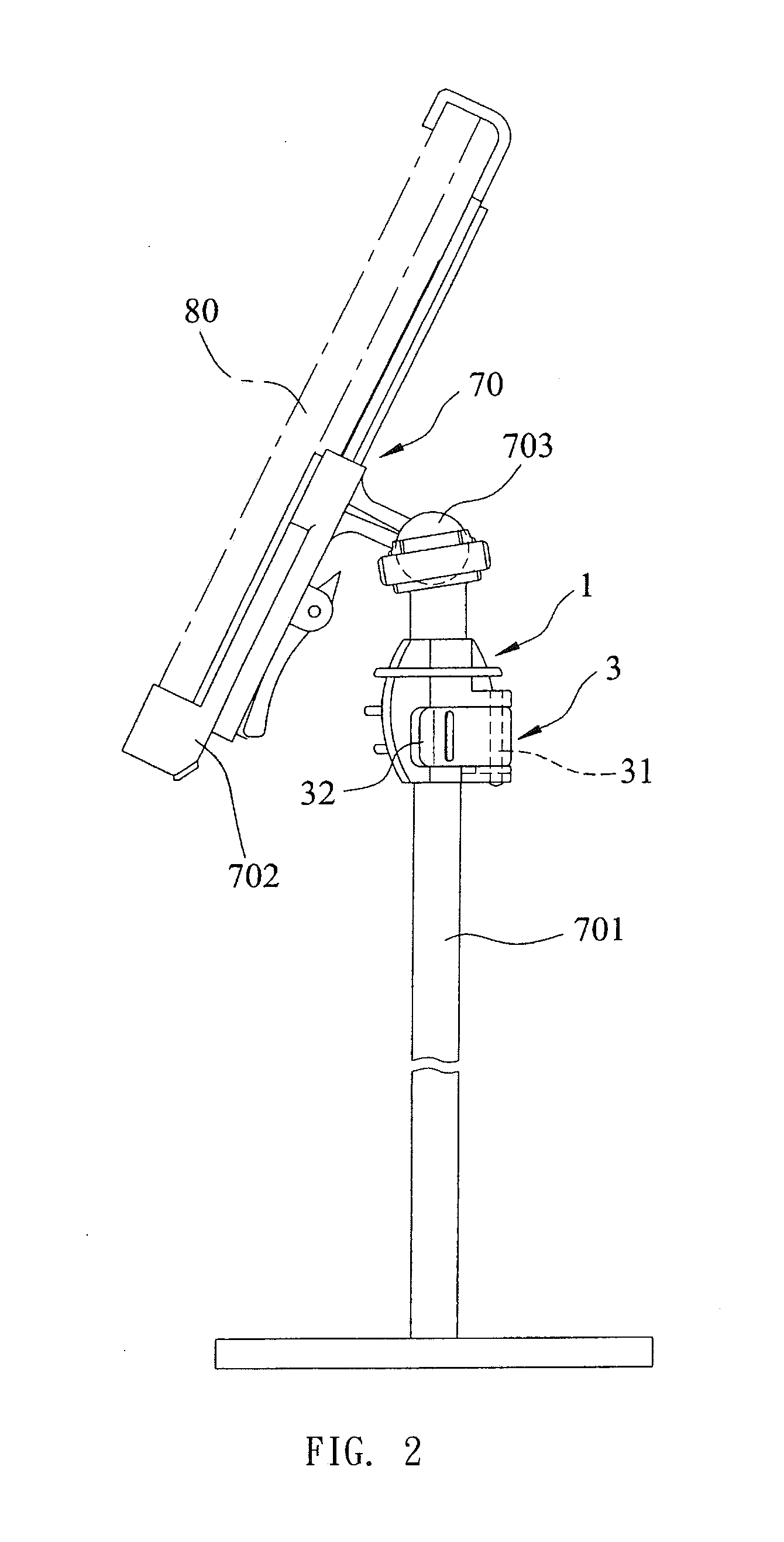
[0018]Referring to the drawings and initially to FIGS. 2-5, a positioning device in accordance with the preferred embodiment of the present invention is used to position a bearing unit 70 which is used for placing a tablet personal computer 80 and the like. The bearing unit 70 includes a support seat 702, a connector 703, and an upright rod 701. The tablet personal computer 80 is placed on the support seat 702 of the bearing unit 70. The connector 703 of the bearing unit 70 protrudes outward from the back face of the support seat 702. The positioning device is mounted on the rod 701 of the bearing unit 70 and is pivotally connected with the connector 703 of the bearing unit 70.

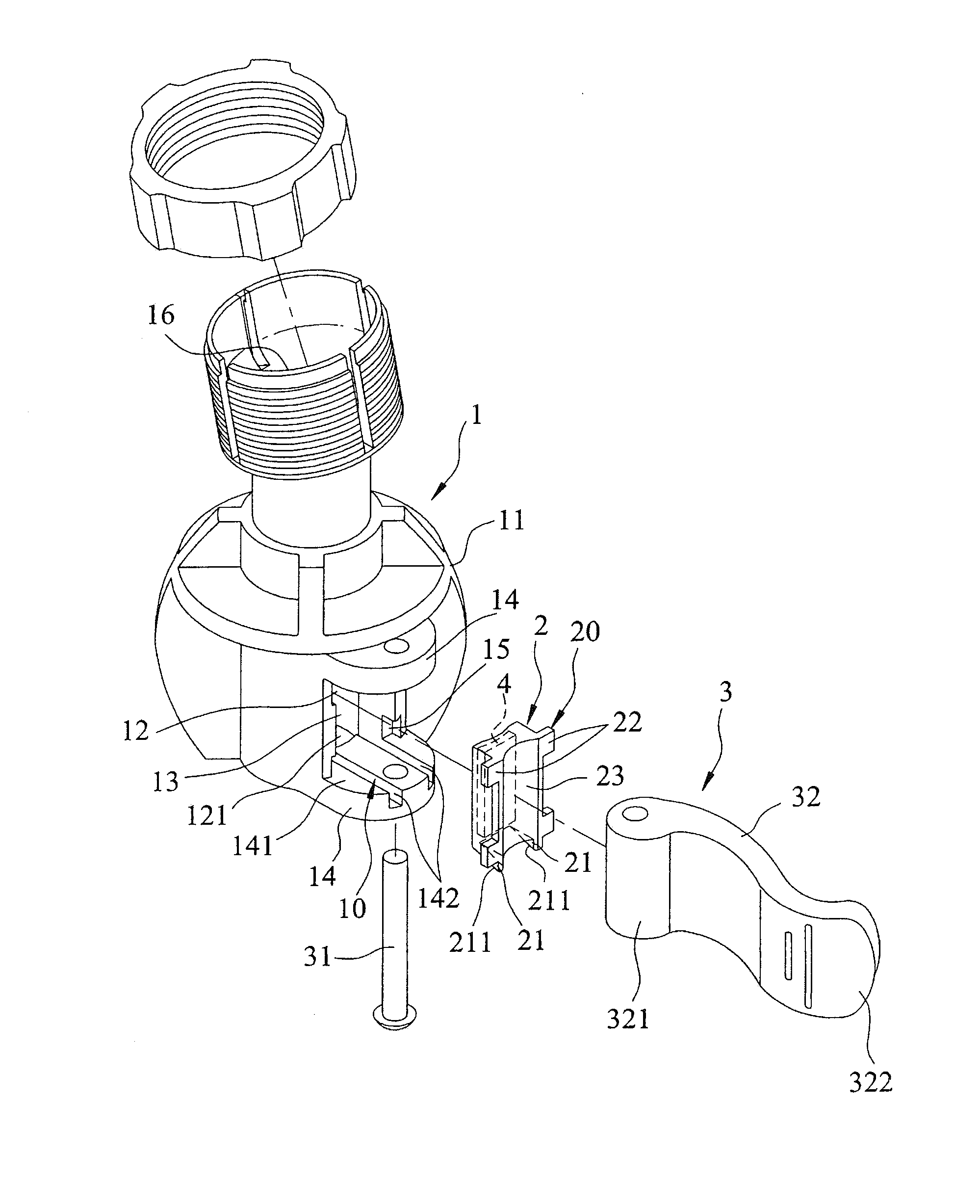
[0019]The positioning device comprises a base 1, a press board 2, an antislip piece 4, and a positioning unit 3.

[0020]The base 1 includes an outer peripheral face 11, an inner peripheral face 12, an opening 13, and a sliding guide module 10. The inner peripheral face 12 of the base 1 defines a mounting space 1...


PUM


Abstract

A positioning device includes a base, a press board, an antislip piece, and a positioning unit. The base includes an opening, and a mounting space. The mounting space is mounted on a rod. The press board is slidably mounted in the opening. The antislip piece is mounted on the press board and is close to the mounting space. The antislip piece is made of elastic material and is softer than the press board. The positioning unit includes a shaft mounted on the base and a driving member rotatably and eccentrically connected with the shaft. The driving member is driven between a pressing position for locking the rod and a releasing position for unlocking the rod. Thus, the user only needs to drive the driving member to lock or unlock the rod so that the rod is locked or unlocked easily and quickly.

Description

BACKGROUND OF THE INVENTION[0001]1. Field of the Invention[0002]The present invention relates to a positioning device and, more particularly, to a positioning device for a rod.[0003]2. Description of the Related Art[0004]A conventional positioning device in accordance with the prior art shown in FIG. 1 is mounted on a rod 520 and comprises a clamping ring 500 and a bolt 510. The clamping ring 500 includes a C-shaped annular wall 501, two spaced fixing plates 502 mounted on two opposite ends of the annular wall 501, and a slit 503 defined between the fixing plates 502. The clamping ring 500 is mounted on the rod 520. Then, the bolt 510 is screwed through the fixing plates 502. When the bolt 510 is screwed tightly to reduce the width of the slit 503, the annular wall 501 of the clamping ring 500 presses the rod 520 so that the rod 520 is locked. When the bolt 510 is unscrewed to enlarge the width of the slit 503, the annular wall 501 of the clamping ring 500 releases the rod 520 so th...

Claims


Application Information

Patent Timeline
IPC IPC(8): F16B2/06
CPCA47C3/28F16B2/06A61B2019/268F16B7/1454A61B2090/571Y10T403/32311
Inventor YU, TSUNG-YAO
Owner YU TSUNG YAO
Why Eureka
Try Eureka