
Anchor system

Inactive Publication Date: 2015-01-15
CEDAR INDS
View PDF9 Cites 1 Cited by
  • Summary
  • Abstract
  • Description
  • Claims
  • Application Information

AI Technical Summary

Benefits of technology

The patent text explains how to create an anchor that can be rotated into a material and secured in place. This is done by using a tether that is connected to the anchor and guides it into position. The invention's goal is to create an improved mechanism for anchoring materials to a surface.

Problems solved by technology

A disadvantage of an anchor which exhibits handedness may be that during tethered restraint of an animal or a moving object the forces transmitted from the tether to the anchor by movement of the animal or moving object can cause the anchor to retreat from the anchoring material.

Method used


Image

  • Anchor system
  • Anchor system
  • Anchor system

Examples


Embodiment Construction

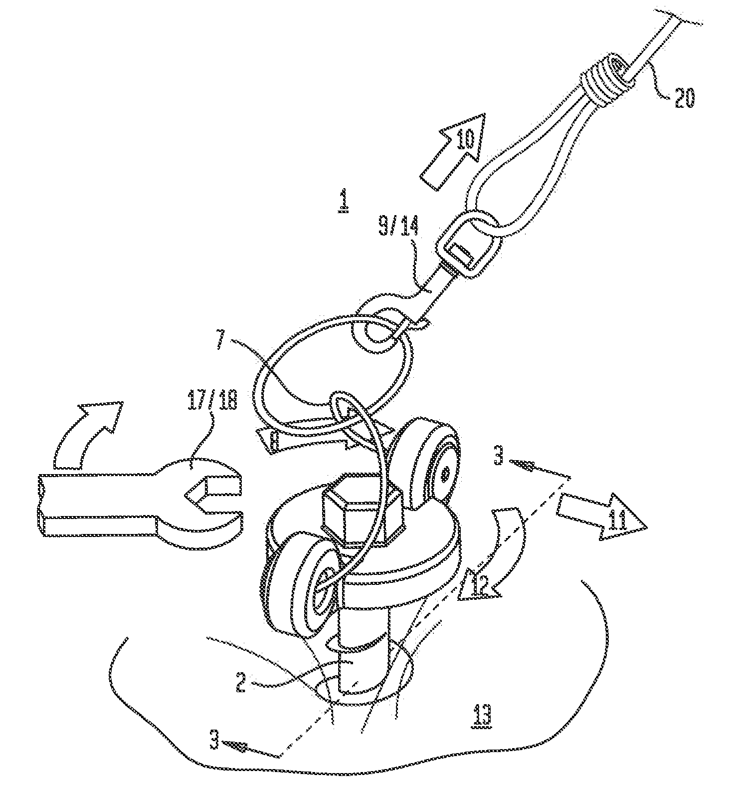
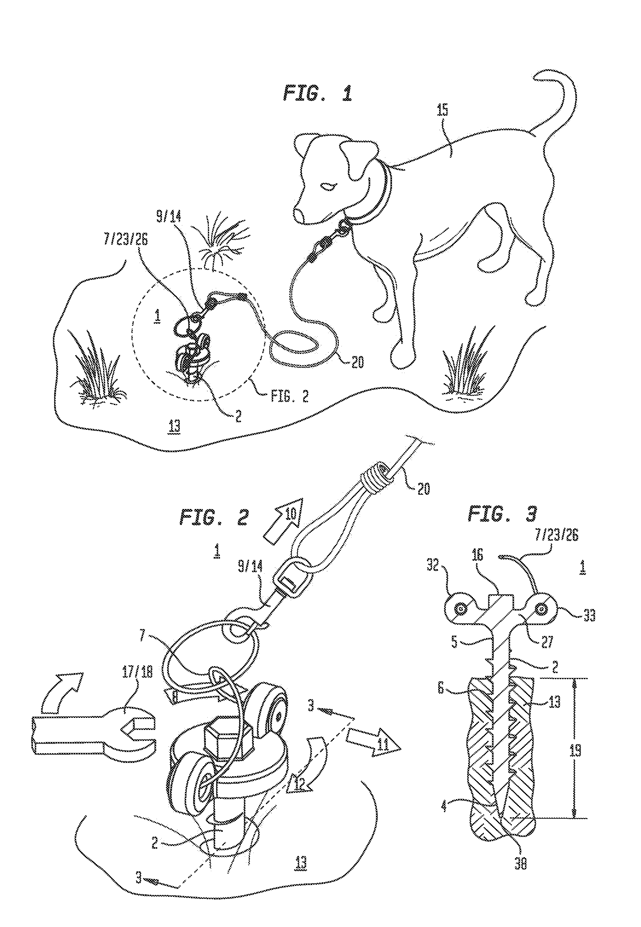
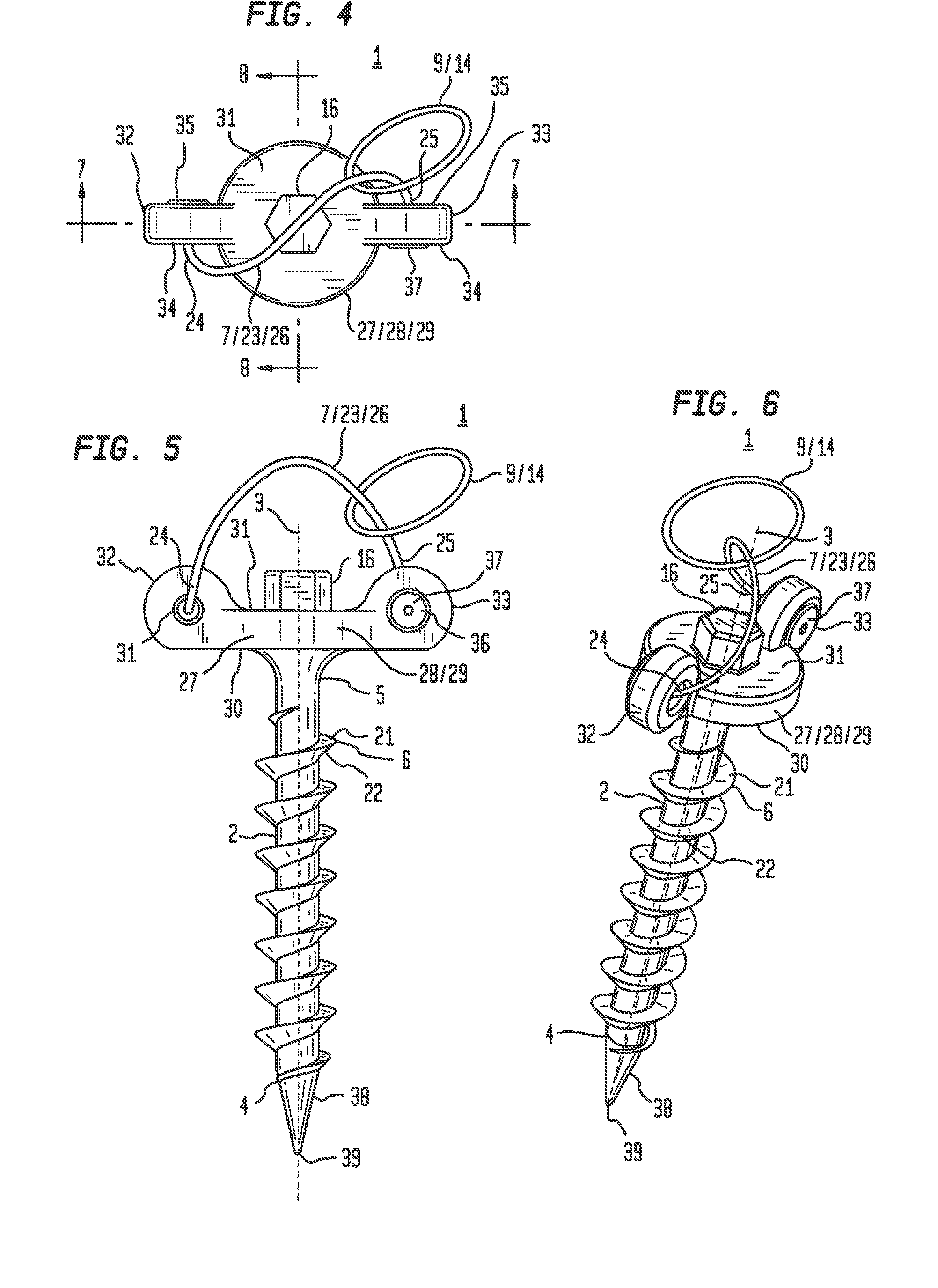
[0015]An anchor in including a cylindrical member having a helical thread which can be advanced into an anchoring material and a tether restraint element having a configuration adapted to guide movement of a tether end movably coupled to said tether restraint toward a position on said tether restraint which directs forces transmitted to the tether restraint element from said tether end in a direction capable of rotationally advancing the elongate cylindrical member into the anchoring material.

[0016]Referring primarily to FIGS. 1 through 8, a particular method of using the inventive anchor (1) includes obtaining an anchor (1) including a cylindrical member (2) having a longitudinal axis (3) which passes through a member first end (4) and a member second end (5), a helical thread (6) coupled to the cylindrical member (2), and a tether restraint element (7) coupled proximate the member second end (5).

[0017]Now referring primarily to FIG. 2, the tether restraint element (7) can have a c...


PUM


Abstract

An anchor in including a cylindrical member having a helical thread which can be advanced into an anchoring material and a tether restraint element having a configuration adapted to guide movement of a tether end movably coupled to said tether restraint toward a position on said tether restraint which directs forces transmitted to the tether restraint element from said tether end in a direction capable of rotationally advancing the elongate cylindrical member into the anchoring material.

Description

I. TECHNICAL FIELD[0001]An anchor including a cylindrical member having a helical thread which can be advanced into an anchoring material and a tether restraint element having a configuration adapted to guide movement of a tether end movably coupled to said tether restraint toward a position on said tether restraint which directs forces transmitted to the tether restraint element from said tether end in a direction capable of rotationally advancing the elongate cylindrical member into the anchoring material.II. BACKGROUND[0002]Conventional anchors useful in tethered restraint of animals or movable objects may include a body configured to advance into an anchoring material by rotation in a first direction and to retreat from the anchoring material by rotation in a second direction depending on the handedness of the body configuration. For example, a right handed configuration advances into an anchoring material when rotated clockwise and retreats when rotated counterclockwise.[0003]A...

Claims


Application Information

Patent Timeline
IPC IPC(8): A01K1/04
CPCA01K1/04
Inventor ROYALS, MICHAEL ANTHONY
Owner CEDAR INDS
Learn More