
Slidable bone plate system

a bone plate system and sliding technology, applied in the field of sliding bone plate system, can solve the problems of abnormal angulation or slippage of the spine, affecting the structure and function of the spinal column, and experiencing extreme and debilitating pain

Active Publication Date: 2005-09-20
NUVASIVE
View PDF26 Cites 313 Cited by
  • Summary
  • Abstract
  • Description
  • Claims
  • Application Information

AI Technical Summary

Benefits of technology

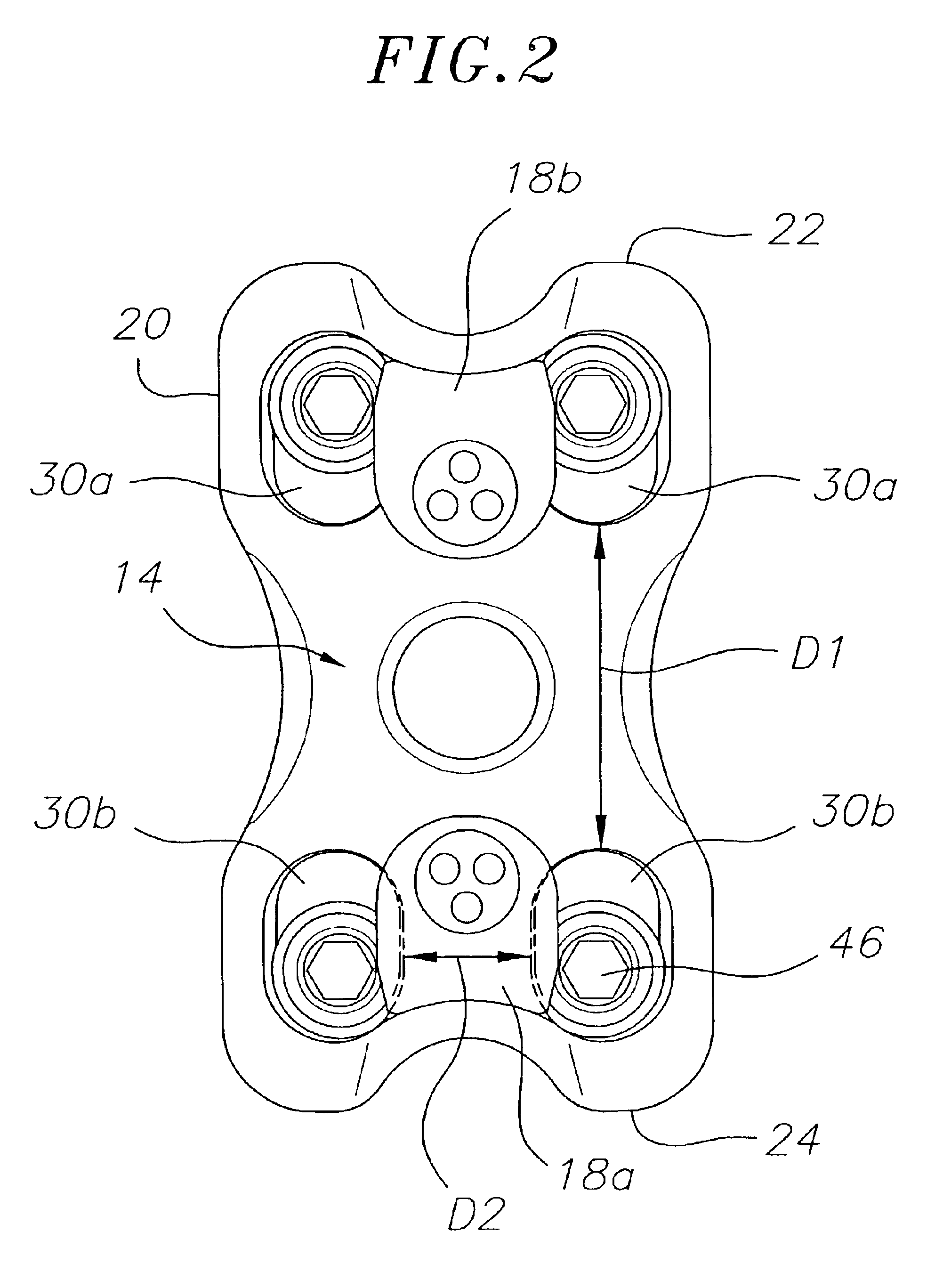
[0005]The present invention is directed to a bone plate system that addresses one or more of the above drawbacks. In one embodiment, the bone plate system comprises a base plate having two generally parallel elongated screw slots extending therethrough. Two bone screws are provided that are capable of securing the base plate to a bone by insertion through the screw slots into the bone. Each bone screw has a screw head and a threaded portion extending therefrom. An interference device is attached to the base plate and retains the bone screws while permitting the bone screws to toggle and to controllably slide in the screw slots of the base plate. This design is particularly useful for joining adjacent vertebral bodies, as it permits controlled settling of the vertebral bodies, thereby enhancing the healing process.

Problems solved by technology

Various types of problems can affect the structure and function of the spinal column.
In addition congenital or acquired deformities can cause abnormal angulation or slippage of the spine.
Patients who suffer from one of more of these conditions often experience extreme and debilitating pain, and can sustain permanent neurologic damage if the conditions are not treated appropriately.
However, there are disadvantages to the present stabilization devices.
Loss of alignment during the healing phase can cause a poor outcome for the patient.
The device must be secure in its attachment to the spine to prevent migration of the implant or backout of the screws from the bone which could result in damage to the structures surrounding the spine, resulting in severe and potentially life threatening complications.

Method used


Image

  • Slidable bone plate system
  • Slidable bone plate system
  • Slidable bone plate system

Examples


Embodiment Construction

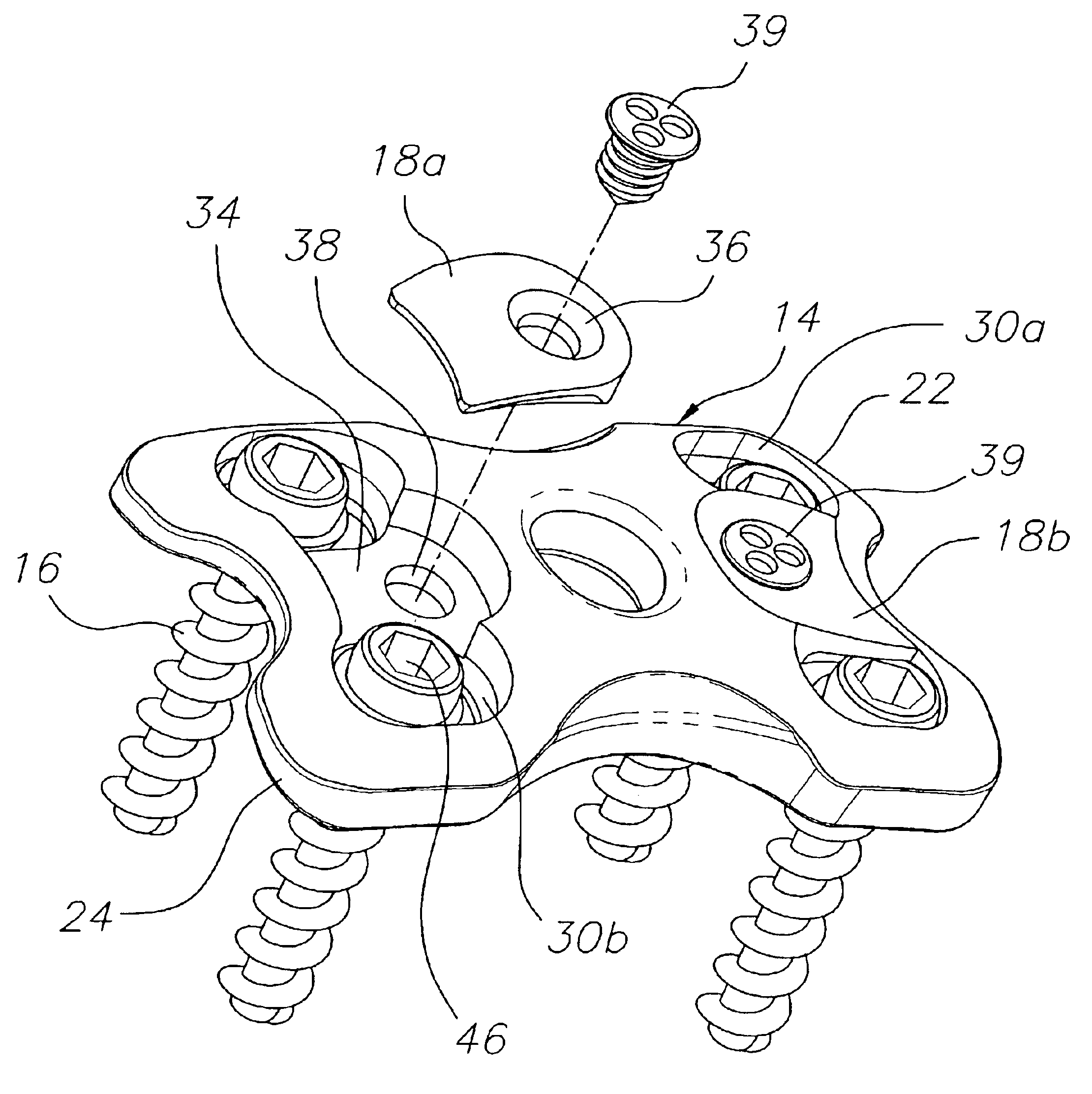
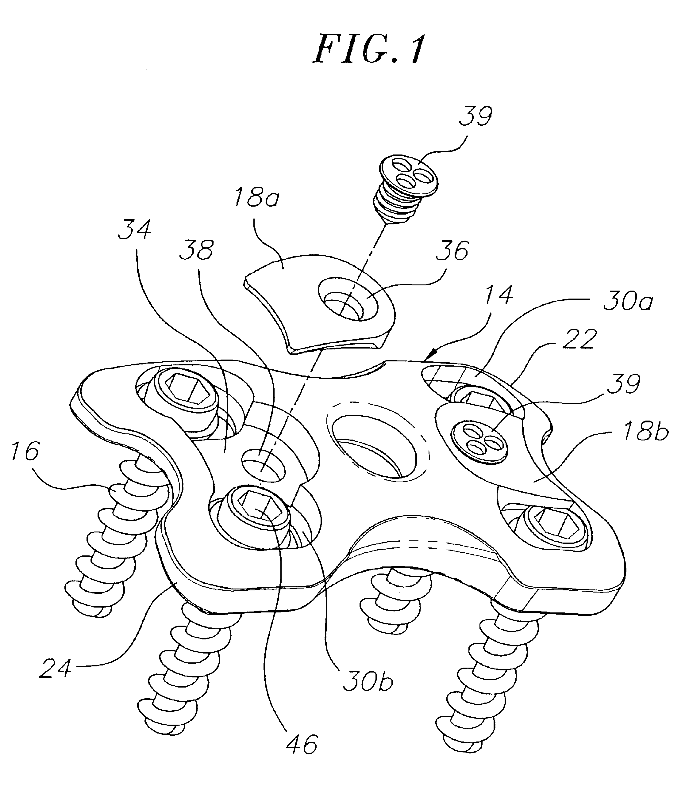
[0012]An exemplary embodiment of a bone plate system according to the present invention is shown in FIGS. 1 to 5. The depicted bone plate system is particularly useful for stabilizing two or more vertebral bodies to allow fusion by holding the vertebral bodies in proper alignment, and thus allowing the bone to heal. The bone plate system of the invention is preferably weight-sharing over a period of at least about three months, and more preferably over a period of at least about six months. As used herein, the term “weight-sharing” as describing the system means that the system allows for partial sharing of the weight of one or more vertebral bodies across a bone graft site.

[0013]Generally, the bone plate system comprises a base plate 14, bone screws 16, and one or more interference devices 18. The base plate 14 is a plate used to connect two or more bones. As used herein, the term “bones” is intended to include both bones and bone fragments or portions. The base plate 14 can be of ...


PUM


Abstract

The invention is directed to a bone plate system. The bone plate system comprises a base plate having two generally parallel elongated screw slots extending therethrough. Two bone screws are provided that are capable of securing the base plate to a bone by insertion through the screw slots into the bone. Each bone screw has a screw head and a threaded portion extending therefrom. An interference device is attached to the base plate and retains the bone screws while permitting the bone screws to toggle and to controllably slide in the screw slots of the base plate. This design is particularly useful for joining adjacent vertebral bodies, as it permits controlled settling of the vertebral bodies, thereby enhancing the healing process.

Description

BACKGROUND[0001]The spinal column of vertebrates provides support to bear weight and protection to the delicate spinal cord and spinal nerves. The spinal column comprises a series of vertebrae stacked on top of each other. There are typically seven cervical (neck), twelve thoracic (chest), and five lumbar (low back) segments. Each vertebra has a cylindrical-shaped vertebral body in the anterior portion of the spine with an arch of bone to the posterior that covers the neural structures. Between each vertebral body is an intervertebral disk, a cartilaginous cushion to help absorb impact and dampen compressive forces on the spine. To the posterior, the laminar arch covers the neural structures of the spinal cord and nerves for protection. At the junction of the arch and anterior vertebral body are articulations to allow movement of the spine.[0002]Various types of problems can affect the structure and function of the spinal column. These can be based on degenerative conditions of the ...

Claims


Application Information

Patent Timeline
Patent Type & Authority Patents(United States)
IPC IPC(8): A61B17/68A61B17/70A61B17/80
CPCA61B17/7059A61B17/8042A61B17/8605
Inventor BRAY, ROBERT S.
Owner NUVASIVE
Learn More