Integrated mechanical handle with quick slide mechanism

a mechanical handle and slide mechanism technology, applied in the field of delivery systems, can solve the problems of frictional resistance, decrease, frictional resistance, etc., and achieve the effects of frictional resistance, frictional resistance, and rapid ra

Inactive Publication Date: 2006-09-12
MEDTRONIC VASCULAR INC
View PDF43 Cites 338 Cited by
  • Summary
  • Abstract
  • Description
  • Claims
  • Application Information

AI Technical Summary

Benefits of technology

[0011]As a result, a proximal end of the prosthesis, which is deployed first, is very gradually released by rotating the slide ring. In this manner, the physician is allowed to verify the accuracy of the deployment position as the prosthesis initially engages the surrounding body lumen.
[0012]However, since dynamic frictional forces are typically lower than static frictional forces, the frictional resistance, due to the forces between the prosthesis and the sheath, decreases once the sheath begins to move. Additionally, as the sheath moves (retracts), more and more of the prosthesis is exposed by the sheath. For this additional reason, the frictional resistance, due to the force between the prosthesis and the sheath, decreases once the sheath begins to move. Further, once the proximal end of the prosthesis has firmly engaged the surrounding body lumen, the relationship between the prosthesis and the surrounding body lumen is largely set, so that deployment can proceed safely and at a more rapid rate.
[0013]Thus, after retraction of the sheath is initiated by axial rotation of the slide ring, which moves axially because of the engagement of threaded pieces, the sheath is further retracted by sliding (manual pulling) of the slide ring. By sliding the slide ring, the sheath is easily and quickly retracted thus rapidly completing deployment of the prosthesis. Rapid deployment of the prosthesis facilitates faster procedure times, thus minimizing the period of time during which blood flow is occluded.

Problems solved by technology

However, since dynamic frictional forces are typically lower than static frictional forces, the frictional resistance, due to the forces between the prosthesis and the sheath, decreases once the sheath begins to move.

Method used


Image

  • Integrated mechanical handle with quick slide mechanism
  • Integrated mechanical handle with quick slide mechanism
  • Integrated mechanical handle with quick slide mechanism

Examples


Embodiment Construction

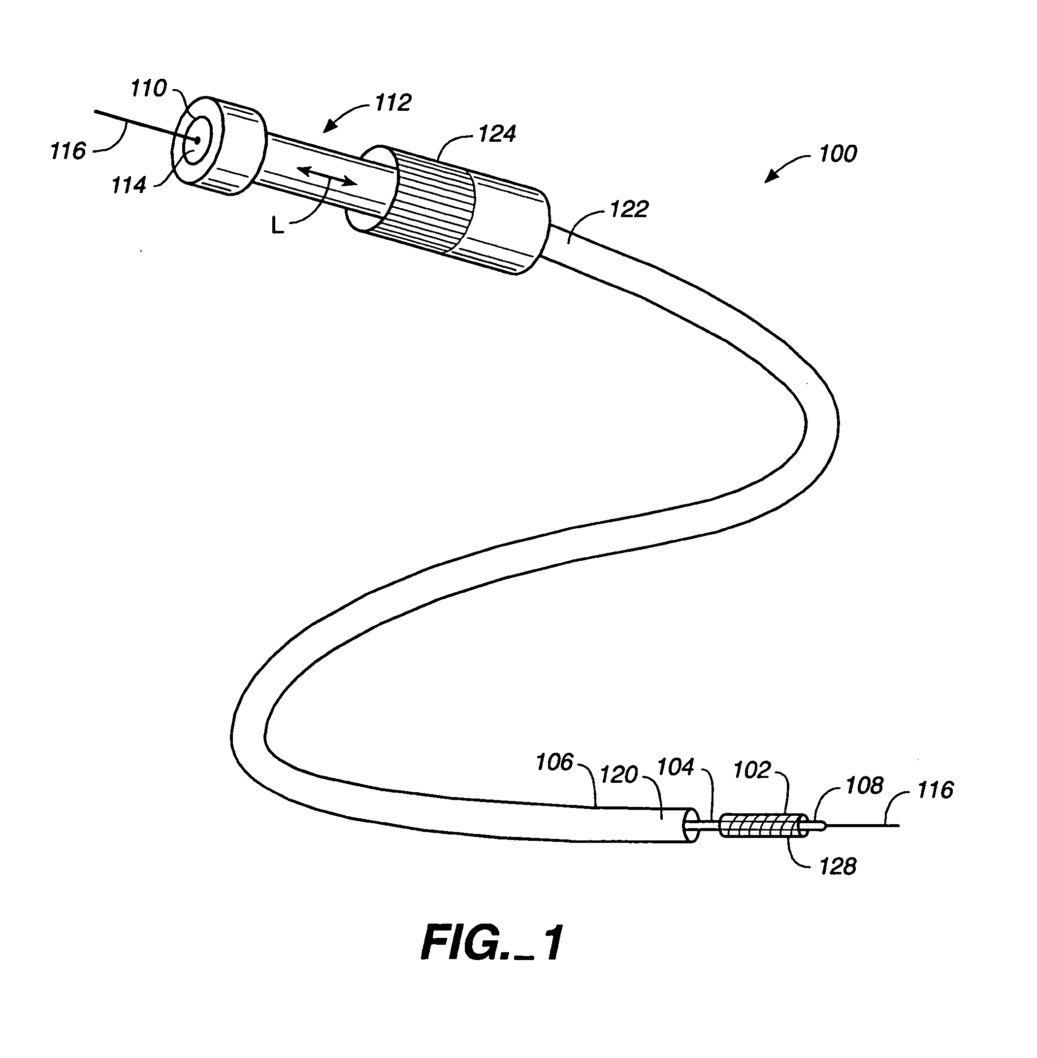
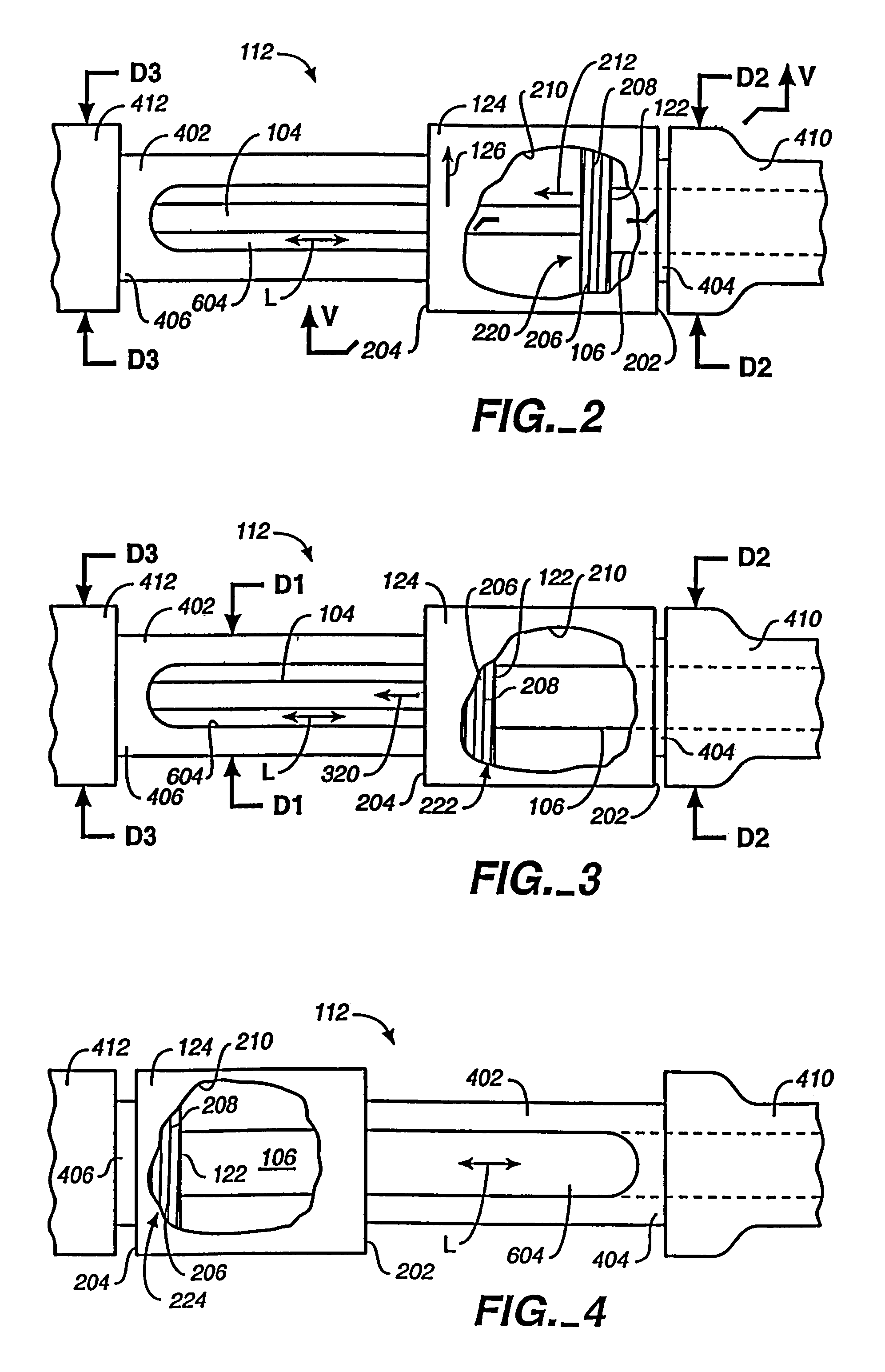
[0042]In one embodiment, a method of deploying a prosthesis 102 (FIG. 1) includes restraining prosthesis 102 within a distal end 120 of a sheath 106. A slide ring 124 of a handle 112 is rotated in a first direction as indicated by an arrow 126 (FIG. 2) to initiate retraction of sheath 106. Slide ring 124 is slid (FIGS. 3, 4) to complete retraction of sheath 106 and deploy prosthesis 102 (FIG. 1).

[0043]In this manner, prosthesis 102 is initially very gradually released by rotating slide ring 124. This allows the physician to verify the accuracy of the deployment position as prosthesis 102 initially engages the surrounding body lumen.

[0044]However, after retraction of sheath 106 is initiated by rotation of slide ring 124 with respect to handle 112, retraction of sheath 106 is completed by sliding of slide ring 124 along the longitudinal axis of handle 112. In this manner, sheath 106 is easily and quickly retracted thus rapidly completing deployment of prosthesis 102. Rapid deployment ...


PUM


Abstract

A delivery system includes a sheath and a handle. The handle includes: a slide shaft having a threaded outer surface; and a hub assembly coupled to the sheath. The hub assembly includes: an inner slider having a thread tooth pivot support; a thread tooth pivotably mounted to the thread tooth pivot support; and a sleeve having a thread tooth press member pressing on the thread tooth, where motion of the sleeve relative to the inner slider pivots the thread tooth on the thread tooth pivot support to engage and disengage the hub assembly with the threaded outer surface.

Description

CROSS-REFERENCE TO RELATED APPLICATIONS[0001]This application is a Continuation-in-part of U.S. patent application Ser. No. 10 / 128,956, filed on Apr. 23, 2002, now U.S. Pat. No. 6,911,039, issued Jun. 28, 2005.BACKGROUND OF THE INVENTION[0002]1. Field of the Invention[0003]The present invention relates to an intra-vascular device and method. More particularly, the present invention relates to a delivery system for deploying endoluminal prostheses within the lumens of the body and to a method of using the same.[0004]2. Description of the Related Art[0005]Vascular aneurysms were the result of abnormal dilation of a blood vessel, usually resulting from disease and / or genetic predisposition, which weakened the arterial wall and allowed it to expand. While aneurysms could occur in any blood vessel, most occurred in the aorta and peripheral arteries, with the majority of aortic aneurysms occurring in the abdominal aorta, usually beginning below the renal arteries and often extending into ...

Claims


Application Information

Patent Timeline
Patent Type & Authority Patents(United States)
IPC IPC(8): A61F2/06A61M25/00A61F2/82A61F2/84
CPCA61F2/95A61F2/966A61M25/00A61M2025/09116A61M2025/0681A61F2002/9517A61F2/9517
Inventor SHIU, BRIANGERSHMAN, ARIGOODSON, BURTWEBER, PAUL L.REPP, RICHARD E.JENSEN, DAVID F.
Owner MEDTRONIC VASCULAR INC
Why Eureka
Try Eureka